







During bring-up, a TFT LCD can have a lit backlight and show a blank white screen. A change of a few pixel clocks to the horizontal back porch can shift the entire image. Even two modules with the same resolution can need different initialization sequences. Each symptom points to a different part of the display, from the optical stack and pixel circuit to the signals sent by the host.
How Does an LCD Backlight Work?
A transmissive LCD uses a backlight as its light source. In a typical edge-lit module, white LEDs feed light into a light guide plate, which spreads it across the display area. Diffuser films smooth out bright spots, while brightness enhancement films direct more of the available light toward the viewer. The LCD panel then controls how much of that light passes through each subpixel.
The backlight driver sets the overall light output through LED current or pulse-width modulation (PWM). The liquid crystal layer controls the gray level of each subpixel. With a fixed backlight setting, a white image and a black image draw roughly the same backlight power. The difference is how much light reaches the viewer. Some light can leak through the panel in its dark state, and the amount can vary with viewing angle. A Mini-LED backlight improves black levels by dimming dark regions independently. Depending on the design, the backlight may have hundreds or thousands of zones, with the pixels in each zone sharing its light output.
LCD Screen Components and the Path of Light
The LCD working principle is easiest to follow from the backlight toward the viewer. A typical color TFT LCD has six functional parts along this path.
| Component | Role in the display |
|---|---|
| LED backlight unit | Provides an even field of white light using LEDs and optical films. An edge-lit design also uses a light guide plate. |
| Rear polarizer | Passes light polarized along one axis. |
| TFT array glass | Carries the row and column wiring, thin-film transistors, and transparent pixel electrodes. |
| Liquid crystal layer | Changes the polarization state of the incoming light in response to the voltage at each subpixel. |
| Color filter and front glass | Gives the subpixels their red, green, and blue spectral characteristics. |
| Front polarizer | Acts as the analyzer. Its transmission axis determines how much of the light leaving the cell can pass through. |
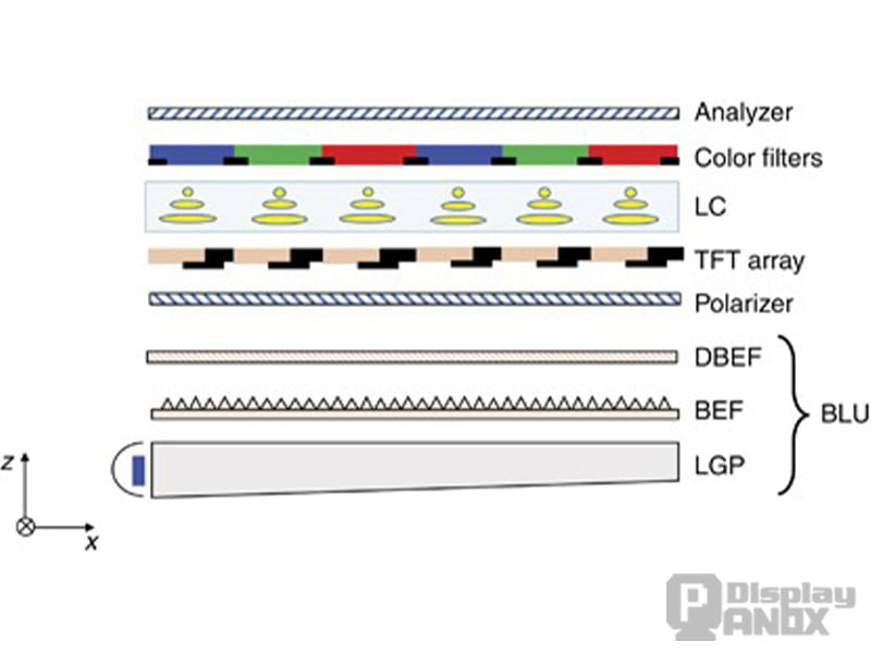
In a typical crossed-polarizer design, the two transmission axes are 90° apart. Two ideal crossed polarizers block light when its polarization stays unchanged between the films. The liquid crystal layer makes the amount of transmitted light adjustable.
The gap between the glass substrates is only a few micrometers. A gap of 3–5 µm is representative of many designs. Tiny beads or patterned spacers keep it uniform. Variations in the gap affect how the cell changes polarization and how quickly it responds, with visible effects on brightness or color. This can also change the gamma correction needed to reproduce the same gray levels. Transparent conductors such as indium tin oxide (ITO) let the electrodes apply the electric field while keeping the active area transmissive.
How Liquid Crystals Control Brightness
A Normally White TN Cell
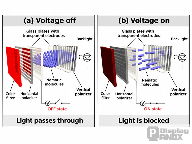
A twisted nematic (TN) cell provides a simple example. Its two alignment layers orient the liquid crystal molecules at right angles on opposite sides of the cell. At zero applied voltage, the orientation twists about 90° through the layer. Light from the rear polarizer follows that twist and reaches the front polarizer with the right orientation to pass through. The subpixel appears bright, which is why this arrangement is called normally white.
Once the drive voltage exceeds the cell's threshold, the electric field begins to tilt the molecules and reduce the twist. At a sufficiently high voltage, much of the liquid crystal aligns with the field. The light's polarization changes much less, and the front polarizer blocks most of it. Drive levels between the bright and dark states produce intermediate transmission. The panel's gamma settings map digital gray levels to the voltages needed for the intended brightness steps.
IPS, VA, and Response Time
In-plane switching (IPS) uses a field that mainly turns the molecules in the plane of the glass. Vertical alignment (VA) starts with the molecules nearly perpendicular to the substrates and tilts them under drive. Multi-domain designs help manage how contrast and color change with viewing angle. Many IPS and VA panels are normally black, with low transmission in the resting state. The panel's drive specifications define the voltage-to-transmission relationship for the particular mode.
Liquid crystal transitions typically take milliseconds, and the same transition can take longer near or below freezing as the material becomes more viscous. Overdrive can speed up a transition by briefly applying a stronger drive level. Black-frame insertion or backlight strobing shortens the portion of each frame that remains visible, reducing motion blur associated with holding the image on screen.
How Does a TFT LCD Work at the Pixel Level?
In an older passive-matrix LCD, row and column electrodes address the cells at their intersections. With a large number of rows, maintaining distinct gray levels and avoiding crosstalk becomes harder. A TFT LCD adds a switch at each subpixel. In a conventional design, the circuit includes a thin-film transistor, a storage capacitor (Cs), and the capacitance of the liquid crystal cell (Clc).
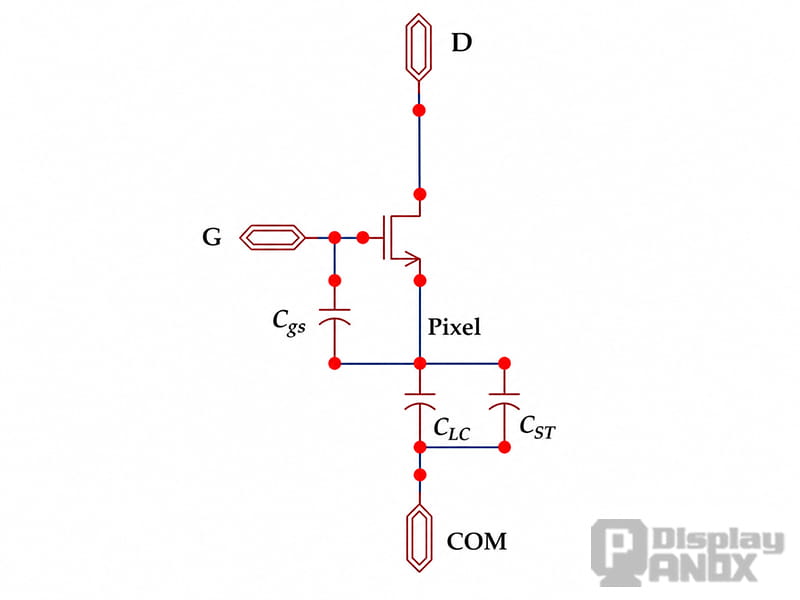
The gate driver selects one row at a time. While that row is active, the source driver applies the analog voltages for its subpixels. Once the gate line turns off the transistors, the capacitances hold the voltages until the row is addressed again. The panel keeps scanning even when the picture is static because the stored charge gradually leaks and the cells need periodic drive. A failed subpixel circuit can leave a bright or dark dot. A row or column drive fault can affect a whole line.
How Do LCD Screens Display Color?
A conventional color pixel is made of red, green, and blue subpixels. Each filter passes its own part of the backlight spectrum, and each liquid crystal cell sets the intensity of that color. The three light outputs combine to form the visible color. With 8 bits per channel, there are 256 levels for each primary and 16,777,216 possible RGB combinations. An 800 × 480 RGB panel has 384,000 pixels and, at one transistor per subpixel, 1,152,000 TFTs.
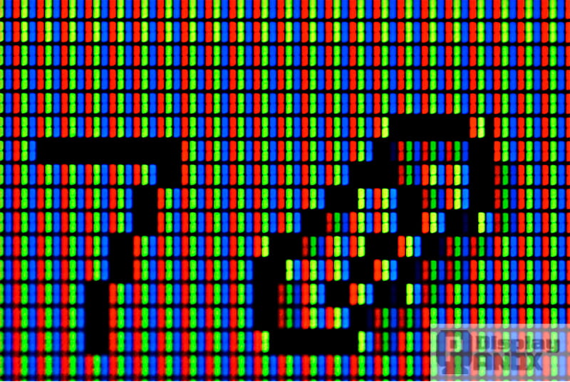
Only part of each subpixel's footprint transmits light. The TFT, metal traces, and black matrix occupy some of the area. The transmitting fraction is called the aperture ratio. At a finer pixel pitch, those features can take up more of the available area if their dimensions stay similar. A lower aperture ratio can require a stronger backlight to reach the same screen luminance.
How the Host Sends an Image to the Panel
The location of the framebuffer is a useful way to understand the difference between common embedded display interfaces.
| Interface | Where the image is held | Typical host setup and use |
|---|---|---|
| SPI or 8080-style MCU parallel | Graphics RAM (GRAM) in the display controller | The host sends commands and updates a selected window. Common in small modules around 240 × 320 to 320 × 480, including units built around ILI9341 or ST7789-family controllers. |
| Parallel RGB | Host framebuffer in internal RAM or external SDRAM or PSRAM | An LCD controller such as STM32 LTDC sends a continuous pixel stream. Common in embedded and industrial HMI designs with modules from 480 × 272 to 1024 × 600. |
| Panel LVDS or MIPI DSI | Typically a host framebuffer for streaming modes | A compatible display transmitter, PHY, or bridge sends data over a serial link. LVDS and D-PHY-based DSI use differential pairs. Common in tablets, vehicle displays, and higher-resolution products, including many 720p and larger panels. |
A module with GRAM refreshes its panel even while the host bus is idle. The host can update only the part of the image that changes, although full-screen updates are limited by bus bandwidth. With a conventional parallel RGB panel, the host streams each frame whether or not the image changes. LVDS panel links and MIPI DSI serialize data and reduce the number of signal conductors compared with a wide RGB bus. DSI video mode streams image data with display timing, while command-mode modules with local memory can support region updates.
A single 800 × 480 framebuffer takes 768,000 bytes in RGB565 and 1,152,000 bytes in packed RGB888. Row padding or a 32-bit storage format increases the allocation. External RAM is often needed when the MCU has limited internal memory or the design uses two full framebuffers.
Panox Display's 4.3-inch 800 × 480 IPS TFT LCD is an example of a panel with a 24-bit parallel RGB input. The system cost and pin-count trade-offs are covered in the parallel RGB interface guide.
Pixel Clock, Data Enable, and Sync Signals
A parallel RGB bus carries a pixel clock (PCLK, also called DCLK), the pixel data lines, and the timing signals required by the panel. A 24-bit interface carries RGB data on DATA[23:0]. HSYNC marks the horizontal line timing, VSYNC marks the vertical frame timing, and Data Enable (DE) marks the active pixel window.
What the Front and Back Porches Do
Starting at the horizontal sync pulse, a line runs through the sync pulse, back porch, active pixels, and front porch. A frame follows the same pattern in units of lines. The blanking intervals date back to CRT raster timing. On an LCD link they set the boundaries of the active image and accommodate the timing needs of the panel. A wrong porch setting can shift or crop the picture even when the active resolution is correct.
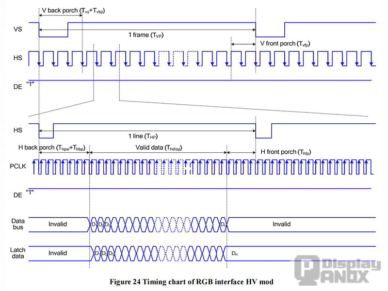
In DE mode with active-high DE, the panel accepts pixel data during the high portion of DE and samples it on the specified PCLK edge. Some panels need only DE and PCLK alongside the data bus for this mode. In sync mode, the panel locates the active area from HSYNC, VSYNC, and its configured offsets. The datasheet specifies which signals the module needs, their polarities, and whether pixel data is sampled on the rising or falling clock edge.
Calculating the Pixel Clock for an 800 × 480 Panel
The pixel clock covers the full line and frame, including blanking. In this 60 Hz example, the horizontal timing is 800 active pixels plus 1 sync clock, 88 back-porch clocks, and 40 front-porch clocks, giving 929 clocks per line. The vertical timing is 480 active lines plus 1 sync line, 32 back-porch lines, and 13 front-porch lines, giving 526 lines per frame.
PCLK = horizontal total × vertical total × refresh rate = 929 × 526 × 60 = 29,319,240 Hz, or about 29.3 MHz.
These values illustrate the calculation. The selected module's timing table supplies the values for an actual design. The STM32 HAL LTDC example below shows how the sync widths and accumulated timing fields are entered. LTDC counts from zero, so the corresponding fields use a value one less than the count. The board configuration sets the pixel clock, signal polarities, framebuffer address, and layer pixel format separately.
/* Fill the STM32 HAL LTDC timing fields and return the target PCLK in Hz. */
static uint32_t set_example_timing(LTDC_InitTypeDef *init)
{
    const uint32_t h_active = 800;
    const uint32_t h_sync = 1;
    const uint32_t h_back_porch = 88;
    const uint32_t h_front_porch = 40;
    const uint32_t v_active = 480;
    const uint32_t v_sync = 1;
    const uint32_t v_back_porch = 32;
    const uint32_t v_front_porch = 13;
    const uint32_t refresh_hz = 60;

    const uint32_t h_total = h_sync + h_back_porch + h_active + h_front_porch;
    const uint32_t v_total = v_sync + v_back_porch + v_active + v_front_porch;

    init->HorizontalSync = h_sync - 1U;
    init->AccumulatedHBP = h_sync + h_back_porch - 1U;
    init->AccumulatedActiveW = h_sync + h_back_porch + h_active - 1U;
    init->TotalWidth = h_total - 1U;

    init->VerticalSync = v_sync - 1U;
    init->AccumulatedVBP = v_sync + v_back_porch - 1U;
    init->AccumulatedActiveH = v_sync + v_back_porch + v_active - 1U;
    init->TotalHeigh = v_total - 1U;

    return h_total * v_total * refresh_hz;
}
The framebuffer format and the physical bus also need to agree with the controller configuration. RGB565 assigns five bits to red, six to green, and five to blue, so the wiring has to follow the panel's mapping for each color channel. If red and blue are swapped, the channel order can often be set through a command such as Memory Access Control (0x36) on modules that support it. Other designs set the order in the host or use fixed pin assignments.
First Power-Up and Common Display Faults
The usual bring-up sequence is to let the power rails stabilize, hold and release reset as specified, initialize the display and start valid image data, then enable the backlight. The reset pulse and any delay after reset come from the module's datasheet. Enabling the backlight after the first valid image prevents the bright white flash that can otherwise appear at startup.
On a command-driven module with GRAM, a typical sequence includes Sleep Out (0x11), the required wake-up delay, Pixel Format Set (0x3A), Memory Access Control (0x36), address window setup (0x2A and 0x2B), and Display On (0x29). Pixel data is sent to the selected window with Memory Write (0x2C). The ILI9341, for example, specifies 120 ms to complete the transition out of sleep. Some modules also require panel-specific power or gamma settings, and an ID read can help identify the controller on a board that supports it.
For PWM dimming, a frequency above 20 kHz can move the switching fundamental above the audible range when the backlight driver supports that frequency. The available dimming range depends on the driver. Camera banding also depends on exposure and sensor readout, so camera-facing equipment benefits from a test with its intended capture settings.
| Symptom | Where to start |
|---|---|
| Backlight on, screen solid white | Check the enable sequence, panel reset and initialization, and the DE waveform in DE mode. Confirm that the controller is reading the intended framebuffer. An RGB565 or RGB888 buffer filled with 0xFF produces a white image. |
| Corrupted image, speckles, or jitter | Check the pixel clock frequency and sampling edge, signal polarities, porch settings, and the flex cable connection. |
| Whole image shifted or edges clipped | Compare the horizontal and vertical front and back porches with the panel's timing table. Verify the active width and height. |
| Red and blue swapped or colors look wrong | Check RGB/BGR order, RGB565 byte order where applicable, and the assignment of data bits to each color channel. Check the required state of unused inputs. |
| Horizontal tear during updates | Check whether the framebuffer is being written or switched during scanout. Double buffering with a swap synchronized to the vertical blanking interval is a common fix. |
| Motion trails in the cold | Check the panel's response at the actual operating temperature and use supported overdrive settings where available. A longer frame interval can give transitions more time to settle if the module supports a lower refresh rate. |
An I²C or SPI link for capacitive touch is separate from the display pixel stream. For a panel with no image, the useful order is to check power and backlight, then reset and initialization, then PCLK and DE, and finally the porches and signal polarities.
Choosing Between LCD and OLED
| Design consideration | TFT LCD | OLED |
|---|---|---|
| Light generation | A backlight supplies light that the liquid crystal cells modulate. | Each subpixel emits its own light. |
| Black level | Dark-state light leakage limits native contrast. Local dimming can improve black levels. | Pixels can turn off, giving a very low black level in a dark environment. |
| Thickness and shape | The backlight and optical films add to the stack. | A thin stack is possible, including flexible designs. |
| Outdoor visibility | A high-output backlight can help. Cover glass reflections and optical bonding also affect readability. | Outdoor readability depends on sustained luminance and reflections. A large bright image can raise power demand. |
| Power use | The backlight is a major load. With a fixed backlight, its power depends mainly on the brightness setting. | Power is more dependent on image content. Dark screens can draw less power. |
| Response | Liquid crystal transitions are usually measured in milliseconds and slow down in the cold. | Emission changes much faster, often on the microsecond scale. |
| Aging and sustained images | Backlight output declines with use. Long-term operation depends on the module and backlight ratings. | Uneven pixel aging can leave a persistent imprint from frequently displayed static content. |
| Cost and supply | Mature options are widely available in common industrial sizes. | Often costs more than a comparable LCD module. Availability depends on the size, form factor, and supplier. |
For an industrial HMI, an outdoor instrument, or a unit that shows the same interface for years, a TFT LCD is often a practical starting point. Panox Display recommends checking screen luminance in the installed enclosure, operating temperature, and host interface against the module specifications. A design expected to stay in production for ten years also needs a supply plan for the specific module. The industrial LCD range includes modules for these applications. OLED is often a better fit when a very thin or flexible stack, deep blacks, and fast pixel response are central to the design.
From the Backlight to a Stable Image
The optical path starts at the backlight. The rear polarizer sets the incoming polarization, the liquid crystal varies it, and the color filters and front polarizer determine the color and amount of light seen from each subpixel. The TFT array writes and holds each voltage as the display scans. On a parallel RGB connection, the host keeps the pixels in step with the panel. Once power and reset are confirmed, looking at PCLK and DE together on an oscilloscope is a practical first check for a DE-mode panel with a blank or shifted image.