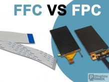

FFC vs FPC: Understanding Flexible Cable Technologies
This article explains the key differences between FFC and FPC, covering structure, routing complexity, durability, and connector/pitch fit to help you choose the right flexible interconnect.

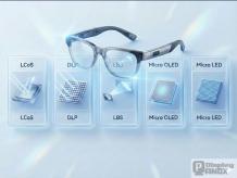
AI Glasses Display Solutions: Micro OLED、Micro LED
Overview of AI glasses microdisplays LCoS, DLP, LBS, Micro OLED, Micro LED and their roles in the XR ecosystem.
What is OLEDoS ?
OLEDoS is an OLED-on-silicon microdisplay enabling compact, bright, low-power visuals for AR/VR, HUD, EVF, and professional imaging.
Micro OLED Becomes the Top Choice for AR Displays?
Micro OLED is becoming the leading AR/XR display choice, offering high clarity and fast response as major brands adopt advanced micro display technology.
Micro OLED: The Next-Generation Lightweight, High-Performance Micro Display Technology
Micro OLED displays—also known as micro OLED screens or OLED microdisplays—are fabricated on a single-crystal silicon wafer that integrates the pixel driver, row/column circuits, SRAM, and T-CON directly on-chip.
OLED vs IPS LCD: Which Display Is Better for Your Business?
OLED and IPS LCD displays are two leading screen technologies, each with unique advantages. Choosing between them depends on factors like color accuracy, cost, brightness, and application needs. For manufacturers, wholesalers, and OEM partners—especially in China—understanding these dif
What Causes OLED Screen Burn and How Can It Be Prevented?
OLED screen burn, also known as burn-in, occurs when static images remain on an OLED display too long, causing permanent discoloration. This common issue affects many manufacturers and users, especially in B2B display applications. Understanding causes, prevention, and solutions is vital for wholes
How Long Does an OLED TV Last?
OLED TVs typically last between 30,000 to 100,000 hours, depending on usage and quality. As leading manufacturers and suppliers in China like Panox Display demonstrate, lifespan varies with panel technology, usage patterns, and manufacturing standards. Also check: OLED What Factors Affect th
What Is 77 in OLED and Why Does It Matter for Manufacturers?
77 in OLED refers to a specific measurement or feature metric used in the OLED display industry, commonly representing panel size, type, or model distinctions. It is important for manufacturers and suppliers like Panox Display because it influences customization, production efficiency, and market a
Panox Display

Browse Articles by Category
OEM SERVICE
Customized Touch Panel

HDMI/Type-C Controller/Driver Board

Custmized LCD/OLED

Free Connectors

Find a Display to Fit Your Application

For More OLED/LCD Panels
If our display fit your application, subscrlbe for monthly Insights
If it`s urgent, try to contact
Whatsapp: +86 18665870665
Skype: panoxwesley
QQ: 407417798


