


Thin Film Transistor Liquid Crystal Display (TFT - LCD) is a mainstream display technology that combines electroluminescent conversion technology with light modulation using liquid crystal technology.
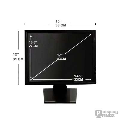
1.Display Size
The display size of a TFT - LCD refers to the diagonal length of the actual visible area, measured in inches (1 inch = 2.54 cm). In earlier Cathode Ray Tube (CRT) displays, the size was also referred to as the diagonal length of the tube itself, but the CRT casing would cover part of the display area, making the actual visible size smaller than the labeled size. Typically, a 17-inch CRT has a visible range of 15.6 to 15.9 inches, while the visible size of a 17-inch TFT-LCD is exactly 17 inches.
2.Aspect Ratio
The aspect ratio is the ratio of the length to the width of the TFT - LCD’s visible area, also known as the screen ratio or display ratio. The actual visible area of a TFT - LCD depends on its aspect ratio. Common aspect ratios for TFT - LCD ‘s are 4:3 and 16:9.
4:3 Aspect Ratio (1.33:1): This was the standard ratio for early displays due to physical constraints of CRT technology, making it suitable for older content.
16:9 Aspect Ratio (1.77:1): This ratio is closer to the natural horizontal and vertical proportions of the human field of view, making it more comfortable for the eyes. It is the international standard for high-definition television (HDTV). In TFT-LCD design, the horizontal dimension is typically labeled as H and the vertical as V.
3.Active Area
The active area refers to the total area on the TFT -LCD where images can be displayed. If the display size and aspect ratio are known, the effective length and width of the display can be calculated using the Pythagorean theorem. For the same display size, a 16:9 TFT -LCD has a smaller effective display area compared to a 4:3 TFT -LCD. Therefore, more 16:9 TFT -LCD’s can be cut from the same size glass substrate. For example, a 1100mm × 1300mm glass substrate can cut only 9 pieces of 19-inch 4:3 TFT -LCDs but can cut 12 pieces of 19-inch 16:9 TFT -LCDs.
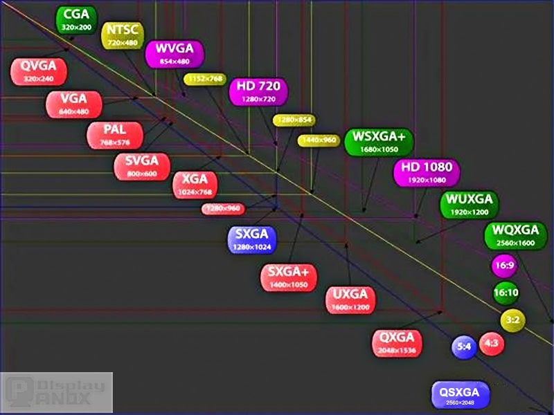
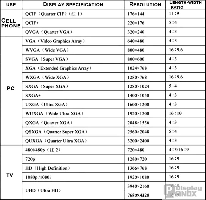
4.Resolution
The resolution of a TFT -LCD indicates the number of pixels in the effective display area. Pixels are the light-emitting points within the display. Resolution is commonly expressed in a multiplication format, such as 1024×768, where 1024 represents the number of pixels in the horizontal direction and 768 represents the number of pixels in the vertical direction. The higher the resolution, the clearer the image. The human eye is more sensitive to vertical resolution, so a higher vertical resolution results in clearer images.
In practice, the best display quality occurs when the resolution of the graphics card output matches the native resolution (physical resolution) of the TFT -LCD panel, achieving "pixel-to-pixel" display.
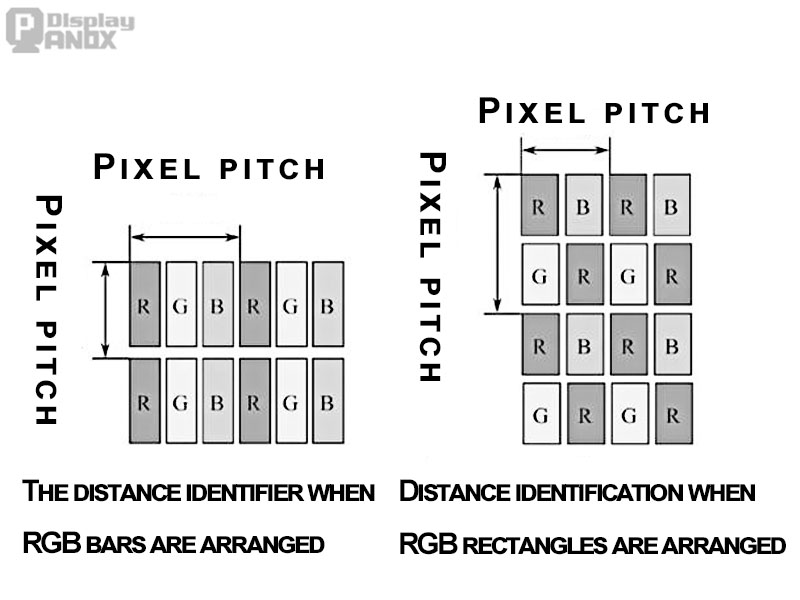
5. Pixel Pitch
Pixel pitch refers to the distance between adjacent pixels in the effective display area, which is the smallest length of the pixel repeating unit. Pixel pitch in TFT -LCD’s is similar to the dot pitch in CRTs. The pixel pitch is fixed and can be calculated by dividing the panel size by the resolution. For color TFT -LCD’s, each pixel contains three sub-pixels: Red (R), Green (G), and Blue (B). The pixel pitch is often marked in a rectangular arrangement, as shown in the diagram (a) for regular RGB strip arrangements. For special pixel arrangements, the pixel pitch may differ. As shown in diagram (b), the pixel pitch for a rectangular RGB arrangement is identified differently.
Pixel pitch and font size are closely related. Smaller pixel pitch results in smaller text. The overall image detail is determined by the pixel pitch—smaller pixel pitch results in a finer image. A more precise measure of image detail is the PPI (Pixels Per Inch) or DPI (Dots Per Inch) value, which represents the number of pixels per unit of area (25.4mm). The smaller the pixel pitch, the larger the PPI (or DPI) value. A higher PPI (or DPI) indicates that the TFT -LCD can display more information for the same display size.
6. Power Consumption
Power consumption in a TFT -LCD is divided into two parts: the backlight and the driving circuitry. Typically, 50% to 80% of the power is consumed by the backlight. The overall power usage of the display depends on factors such as brightness, optical specifications, and the content being displayed. Key methods for reducing power consumption include improving the efficiency of light-emitting devices like LEDs, increasing pixel light transmittance, and using lower power driving technologies.
Related: Low Consumption Display Panel
7. Lifetime
A TFT -LCD's lifespan is primarily determined by the longevity of its light-emitting components, measured in hours (hrs). A typical TFT -LCD can last tens of thousands of hours without issues. With an average daily usage of 5 hours, the display could last up to 10 years. The lifespan is usually evaluated through Mean Time Between Failures (MTBF), which is determined by accelerated aging tests in high-temperature and high-humidity conditions (50°C, 80% humidity). During these tests, brightness gradually decreases. The TFT -LCD's lifetime is defined by the time it takes for the brightness to drop to 50% of its original value. MTBF from these tests is then adjusted to room temperature (25°C) using a factor of 5.73. For example, if the MTBF is 20,000 hours in the accelerated test, the actual MTBF at room temperature is 114,600 hours.
8. Viewing Distance
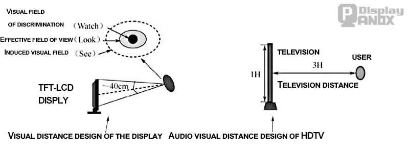
Visual distance design of TFT - LCD products
9. Brightness
Brightness refers to the intensity of light emitted by a TFT-LCD, measured in candelas per square meter (cd/m²). Excessive brightness can lead to visual fatigue, while low brightness reduces contrast between pure black and white, affecting grayscale detail. Brightness uniformity is also critical—high-quality displays feature even brightness with no noticeable dark spots
Related: High Brightness Display Panel
10. Contrast Ratio
The contrast ratio (CR) is the ratio of the brightness of full white to full black, expressed as CR = full white brightness ÷ full black brightness. For example, if full white brightness is 200 cd/m² and full black brightness is 0.2 cd/m², the contrast ratio is 1000:1. A higher contrast ratio results in a more vivid image. The contrast ratio primarily depends on the LCD technology used. In design, lowering the black screen brightness is typically more effective at improving contrast than increasing the white screen brightness.
11. Viewing Angle
The viewing angle of a TFT - LCD is the range within which the contrast ratio drops to 10%. Outside this range, distinguishing between black and white becomes difficult. As shown in the diagram, angles are measured from a normal line perpendicular to the screen, with θLeft, θRight, θUp, and θDown representing the angles to the left, right, up, and down. Typically, the horizontal viewing angles (θLeft, θRight) are wider than the vertical angles (θUp, θDown).
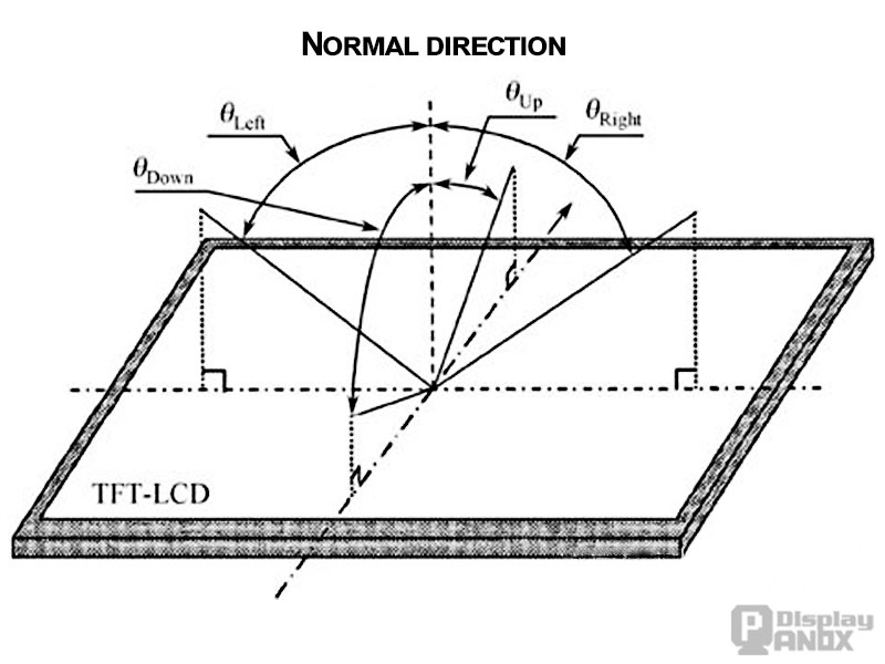
The field Angle of TFT-LCD
12. Response Time
Response time (tRT) encompasses several concepts, including turn-on time (ton), turn-off time (toff), rise time (tr), fall time (tf), and delay time (td). The timing diagram for response time is as follows,
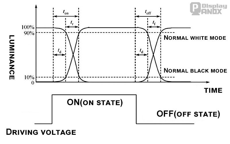
Timing of response time
Turn-on Time (ton): Time for brightness to drop from 100% to 10% (white mode) or rise from 0% to 90% (black mode) when turning on.
Turn-off Time (toff): Time for brightness to rise from 0% to 90% (white mode) or fall from 100% to 10% (black mode) when turning off.
Rise Time (tr): Time for brightness to decrease from 90% to 10% (white mode) or increase from 10% to 90% (black mode) during turn-on.
Fall Time (tf): Time for brightness to increase from 10% to 90% (white mode) or decrease from 90% to 10% (black mode) during turn-off.
Delay Time (td): Time it takes for the brightness to reach 10% of maximum brightness during power-up or power-down.
Related: Low Response Time LCD/Fast LCD
13.Color Gamut
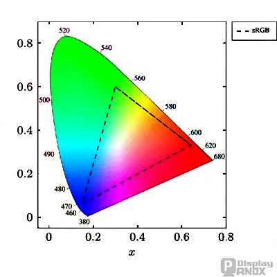
Color gamut refers to the range of colors that a TFT-LCD can display, represented as a region on the chromaticity diagram. The largest color gamut encompasses all colors visible to the human eye, defined by the visible spectrum of light.
CIE-xy chromaticity diagram
The International Commission on Illumination (CIE) uses the CIE-xy chromaticity diagram to describe color gamuts. In this 2D color space, the color gamut of a display device is represented by a triangle formed by connecting the red, green, and blue points. The larger the area of the triangle, the broader the color gamut. The ratio of this triangle's area to the total area of the chromaticity diagram defines the display's color gamut specification.


