







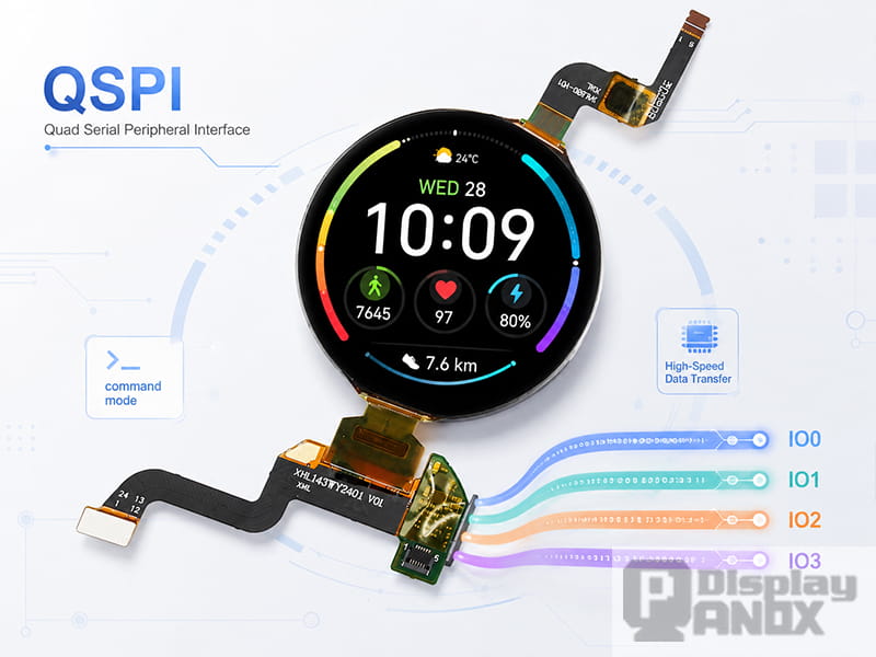
1.43 inch AM-OLED Full Color On-cell PCAP Touch
Open the datasheet of almost any recent smartwatch-class AMOLED and one line keeps repeating in the interface section: QSPI. The same abbreviation shows up on round development boards, rotary knob displays, and a growing number of small TFT modules. For engineers who grew up with classic four-wire SPI, the term looks familiar and unfamiliar at the same time. This guide explains what a QSPI display panel is, where the interface came from, how it moves pixel data in practice, and how it compares with plain SPI and MIPI DSI, using real panels from the Panox Display QSPI product line as reference points.
1.What Does QSPI Mean on a Display Datasheet?
QSPI stands for Quad Serial Peripheral Interface. It keeps the basic structure of SPI — a clock line, a chip-select line, and a synchronous serial data path — and widens the data path from one line to four. On a display module, those four lines usually appear in the pin table as SIO0 through SIO3 or QSPI_SI00 through QSPI_SI03. The datasheet of Panox Display's 2.04-inch AMOLED (model PO204RT448S), for example, lists exactly this arrangement: chip select, serial clock, and four QSPI data inputs feeding the driver IC.
A QSPI display panel, then, is a display module whose driver IC accepts commands and pixel data over this four-lane serial bus. Under the glass it can be an AMOLED, a TFT-LCD, or another panel type; the QSPI label describes the electrical connection between the host processor and the driver IC, while the panel technology underneath is a separate question.
One naming detail is worth knowing before you dive into old MCU manuals. When Motorola coined "QSPI" in the late 1980s — the company filed a patent for a "queued serial peripheral interface" in 1987 — the Q meant queued: an SPI block with a command queue that reduced CPU intervention. The QSPI printed on modern display and flash datasheets means quad. The two share an acronym and little else, and mixing them up has confused more than one engineer reading a legacy reference manual.
2.From Motorola's SPI to Four Data Lines
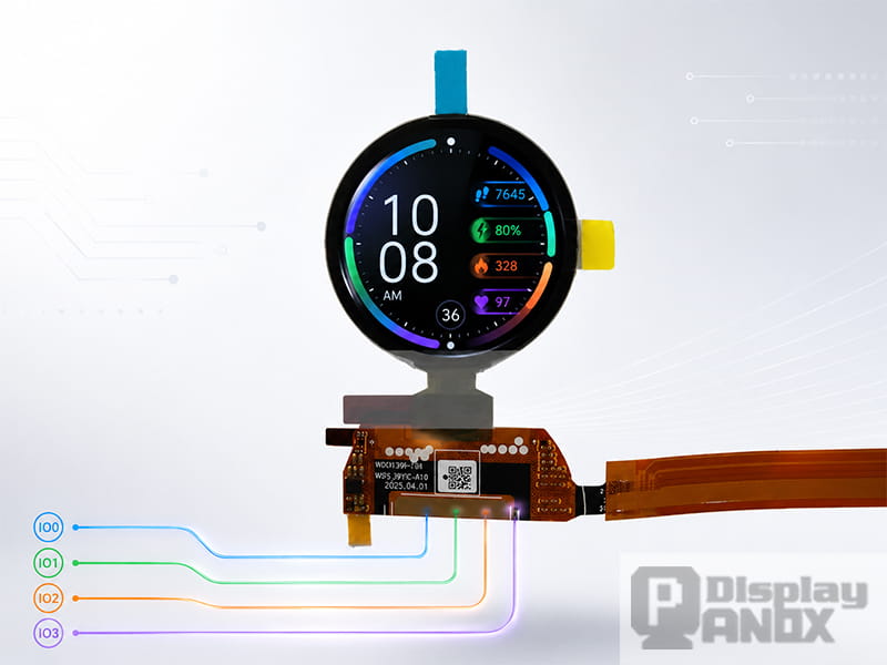
1.39 inch Round OLED 454x454 SPI 800 nits
SPI itself dates back to the mid-1980s, when Motorola introduced it as a simple synchronous link between microcontrollers and peripherals. STMicroelectronics' documentation still describes it the same way today: a Motorola-developed interface that became a de facto standard without ever passing through a formal standards body. Its simplicity made it universal, and nearly every microcontroller made in the past three decades ships with at least one SPI peripheral.
The jump to four data lines came from memory, long before displays were involved. Serial NOR flash vendors needed more read bandwidth while keeping the small pin count that made serial flash attractive in the first place, so they added dual and quad I/O modes that multiplied throughput at similar clock rates. The approach worked well enough that MCU vendors built dedicated QSPI and OctoSPI controllers to talk to these chips. That is the hardware foundation display driver ICs later borrowed: the same four-lane electrical layer, repurposed to carry pixels instead of code.
Display driver IC makers had a strong motive to adopt it. Wearable AMOLED resolutions climbed past the point where a single SPI line could refresh a full frame at acceptable speed, while MIPI DSI — the interface used in phones — demands a differential PHY that most general-purpose microcontrollers simply lack. Quad SPI sat exactly in the gap.
3.How a QSPI Display Interface Works
A typical QSPI display connection uses six signal lines: chip select, serial clock, and the four data lines SIO0–SIO3, usually joined by a reset pin and a tearing-effect (TE) output for frame synchronization. Compare that with a parallel RGB bus, which can consume twenty or more GPIOs before touching control signals, and the appeal for compact products becomes obvious.
Protocol-wise, QSPI panels follow the command model defined by the MIPI Alliance's Display Bus Interface (DBI) and Display Command Set (DCS) — the same command vocabulary used by MIPI DSI panels in command mode. Sleep out is 0x11, display on is 0x29, the drawing window is set with 0x2A and 0x2B, and pixel data flows in through 0x2C. What changes in QSPI operation is how the bits travel: the host sends the instruction and command phase on a single line, then fans the pixel payload out across all four data lines. Engineers often describe this as a 1-1-4 transfer. Open-source display frameworks such as ESPHome document their quad-SPI drivers explicitly as MIPI DBI devices for this reason.
The other defining trait of these panels is that they work in command mode with internal graphics RAM. Driver ICs commonly paired with QSPI — the SH8601 and CO5300 found on many ESP32 AMOLED boards, Raydium's RM69091, and the CH13613 used on Panox Display's 2.04-inch module — integrate a full-frame GRAM. The host writes an update into that memory, and the driver IC's timing controller refreshes the panel from GRAM on its own, typically at 60 Hz. Infineon's application note on low-power graphics describes command-mode operation in exactly these terms: the host updates the panel's onboard frame buffer instead of streaming continuous video. The practical consequences matter. The MCU only transmits when content changes, partial updates are possible, and the processor can sleep between frames while the watch face stays on — a major reason this architecture suits battery-powered wearables so well.
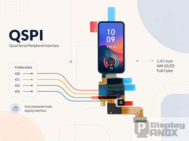
1.47 inch AM-OLED Full Color On-cell PCAP Touch
The easiest way to see why QSPI took over the wearable segment is to run the numbers on an actual panel. A 466 × 466 AMOLED at 16 bits per pixel carries about 3.5 Mbit per frame. Updating the full frame 30 times per second therefore needs roughly 104 Mbps of raw throughput, before any protocol overhead.
Classic single-line SPI on display driver ICs typically tops out somewhere between 40 and 80 MHz, which translates to 40–80 Mbps. That is enough for a 240 × 240 status screen and clearly short for a 466 × 466 watch face at fluid frame rates. Run the same clock over four lines and the picture changes: 40 MHz becomes 160 Mbps, 60 MHz becomes 240 Mbps, and full-frame updates at 60 Hz-class rates move within reach. Published results back this up — Waveshare's LVGL demos on 466 × 466 AMOLED boards driven by an ESP32-S3 over QSPI report 50 to 60 frames per second in dynamic scenes.
MIPI DSI plays in a different league, with up to 1.5 Gbps per data lane according to Infineon's D-PHY documentation, and it remains the right answer for phone-resolution panels and sustained video. It also requires a DSI host controller and differential routing that most MCUs and many compact PCBs cannot offer.
| Interface | Data lines | Realistic throughput | Typical fit |
|---|---|---|---|
| SPI | 1 | 40–80 Mbps | Small status displays up to about 240 × 240 |
| QSPI | 4 | 160–320 Mbps | Wearable AMOLED, 368 × 448 to 466 × 466 class |
| MIPI DSI | 1–4 differential lanes | Up to 1.5 Gbps per lane | Phone-class resolutions and video content |
As a working rule: below roughly 240 × 240, plain SPI is comfortable; in the wearable band from about 368 × 448 up to 466 × 466, QSPI is the sweet spot; beyond that, or wherever continuous video matters, MIPI DSI or RGB takes over.
5.Why Smartwatch AMOLED Panels Standardized on QSPI
Bandwidth alone doesn't explain the adoption. Three additional factors pushed the wearable industry toward quad SPI.
The first is host availability. Espressif's ESP32-S3 drives QSPI AMOLEDs directly through its LCD peripheral, and a whole generation of development boards — Waveshare's 1.32-inch, 1.75-inch, and 1.8-inch AMOLED boards among them — pairs the chip with SH8601 or CO5300 driver ICs over QSPI precisely because it saves I/O pins. On the STM32 side, the QUADSPI and OctoSPI peripherals allow the command, address, and data phases to run on one, two, four, or eight lines each, which is flexible enough to generate display transactions. Nordic's nRF52 series has been shown driving 360 × 360 panels through its QSPI block as well. In short, the interface works with mainstream, inexpensive silicon that design teams already use.
The second is the wiring itself. On a smartwatch FPC a few millimeters wide, six single-ended signals route far more easily than impedance-controlled differential pairs. Riverdi, which builds SPI/QSPI modules up to 15.6 inches around Bridgetek EVE controllers, frames the same trade-off for industrial designs: serial host interfaces exist for products where GPIO count, PCB routing, or connector space rules out a wide video bus.
The third is power, which loops back to the GRAM architecture described earlier. A command-mode QSPI AMOLED lets the system idle with a static watch face displayed from internal memory, waking the host only when content changes. For a device that lives on a 300 mAh battery, that behavior is worth more than any single spec line.
6.QSPI Display Panels at Panox Display
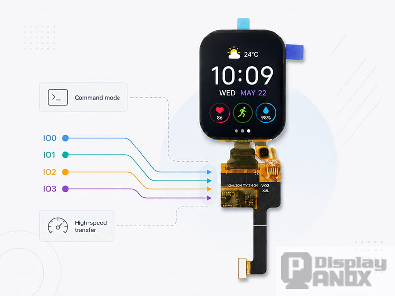
2.04 inch AM-OLED Full Color On-cell PCAP Touch
The QSPI tag page at Panox Display collects the panels in our range built around this interface family, and three of them illustrate the segment well.
The 1.43-inch round AMOLED with on-cell PCAP touch is the most representative QSPI product in the lineup: 466 × 466 resolution — the same class used in the bandwidth calculation above — driven over QSPI, with high luminance and the deep contrast typical of AMOLED. It targets smartwatches and other wrist-worn devices, and a demo kit is available for evaluation.
The 2.04-inch AMOLED with on-cell capacitive touch comes from Truly with a 368 × 448 portrait resolution, a CH13613 driver IC communicating over Q-SPI, 700 cd/m² typical luminance, and an operating range of -30 to 70 °C. The combination of sunlight readability, wide temperature tolerance, and a four-lane serial interface makes it a strong fit for sports watches and outdoor handheld equipment, and it works with MCUs including STM32, GD32F, AVR, Arduino, and ARM-class parts.
The 1.2-inch round OLED takes a flexible approach to the same question: the EDO-made panel with a Raydium RM69091 driver supports MIPI, SPI, and QSPI on one module, selectable through interface-mode pins. With 390 × 390 pixels at 325 PPI, a 100,000:1 typical contrast ratio, and integrated on-cell touch, it lets a project start on plain SPI during early firmware bring-up and move to QSPI once frame-rate demands grow.
Two close relatives sit on the same tag page for projects that stay within single-lane budgets: the 1.39-inch round OLED at 454 × 454 with 800-nit brightness and the compact 1.47-inch 194 × 368 module. Since all of these share the DCS command vocabulary, moving between them is mostly a matter of initialization code and window coordinates.
Panox Display perspective: interface choice is where many wearable projects stall, so we supply more than the bare panel. Every QSPI display we sell ships with the panel datasheet, driver IC documentation, circuit schematics, and initialization code, and our engineers can provide connectors, demo kits, customized cover glass or touch panels, and controller boards when a project needs them. For teams still weighing serial options, our guides on the SPI interface and the MIPI interface cover the neighboring choices in more depth.
A few points decide whether integration goes smoothly. Confirm first that your MCU's quad-capable peripheral can generate display transactions and pair with DMA; some flash-oriented QSPI blocks restrict custom instruction formats, so the reference manual deserves a careful read before the PCB is finalized. Budget memory for rendering — a full 466 × 466 frame at 16 bpp needs about 434 KB, which on an ESP32-S3 usually means PSRAM or slice-based rendering through a graphics library such as LVGL. Wire up the TE pin and synchronize writes to it if the UI shows motion, otherwise tearing will appear during animations. And use the vendor's initialization sequence exactly as provided; on AMOLED, brightness is set through DCS command 0x51, since there is no backlight to dim.
Learn more: QSPI Display Panel Applications: Where Quad SPI AMOLED Screens Make the Most Sense
FAQ
Is QSPI the same as the "4-wire SPI" mentioned in older display documents?
They differ. The four wires in classic display SPI are clock, data, chip select, and the D/C (data/command) line — still a single data lane. QSPI refers to four parallel data lines, and the data/command distinction moves into the command phase of the protocol, so a dedicated D/C pin disappears.
Do I need a MIPI DSI host to drive a QSPI AMOLED?
No. That is much of the point: QSPI panels follow the MIPI DCS command set while remaining electrically compatible with the quad-SPI peripherals found on mainstream MCUs such as the ESP32-S3, STM32 families with QUADSPI or OctoSPI, and Nordic nRF52 devices.
Can a QSPI display panel play video?
Short clips and UI animations at wearable resolutions run well, as the 50–60 fps LVGL results on 466 × 466 boards show. Sustained high-resolution video is better served by MIPI DSI or RGB interfaces with their much higher lane bandwidth.
Which driver ICs support QSPI?
Common examples include the SH8601, CO5300, CH13613, and Raydium's RM69091. Always confirm in the driver IC datasheet, since many chips expose several interfaces selected by IM pins or configuration registers.
Can one panel support both SPI and QSPI?
Some can. Panox Display's 1.2-inch round OLED (E120A390QSR) supports MIPI, SPI, and QSPI on the same module, which is convenient for staged development.
Does Panox Display provide initialization code for QSPI panels?
Yes. Datasheets, IC documentation, schematics, and initial code come with development and batch orders, and demo kits or HDMI/Type-C controller boards are available where a project needs a faster path to a working screen.



