







A Raspberry Pi OLED screen can be anything from a one-inch monochrome status module to a full-color display used for a Linux desktop, camera preview, control panel, or portable instrument. These products may share the OLED name, but they do not connect to Raspberry Pi in the same way.
Small SSD1306 and SH1106 modules normally communicate through GPIO using I²C or SPI. Larger AMOLED and full-color OLED panels usually require a video interface and a controller board that converts HDMI or another Raspberry Pi output into the native interface of the panel.
Understanding this difference is the first step toward choosing a display that matches the required size, resolution, software environment, and application.
What Is a Raspberry Pi OLED Screen?
An OLED screen uses self-emissive pixels, so the panel does not require the separate backlight found in a conventional LCD. For small embedded displays, this makes OLED modules useful for compact interfaces with dark backgrounds, sharp text, low component count, and good readability at wide viewing angles.
The term “Raspberry Pi OLED screen” usually refers to one of two display systems.
GPIO OLED modules
These are commonly available in sizes such as 0.91, 0.96, 1.3, and 1.5 inches. Typical resolutions include 128 × 32 and 128 × 64 pixels. The module connects to the Raspberry Pi GPIO header through I²C or SPI and is controlled by Python code.
SSD1306 is one of the best-known controllers in this category. Solomon Systech describes it as a single-chip CMOS OLED/PLED controller designed for a 128-segment by 64-common dot-matrix display.
Full-color OLED panels
Larger OLED and AMOLED panels are intended to display graphical interfaces, desktop output, video, photographs, camera feeds, or touch applications. Their native interfaces may include MIPI DSI, RGB, LVDS, or eDP.
These panels cannot normally be connected to four GPIO pins and controlled like an SSD1306 module. A controller board, compatible firmware, power circuit, and correctly matched cable are usually required.
Small OLED Module or Full-Color OLED Display?
The correct display architecture depends on what needs to appear on the screen.
| Requirement | GPIO OLED Module | Full-Color OLED Panel |
|---|---|---|
| Typical content | Text, icons, sensor values | Desktop UI, video, images, camera feed |
| Common resolution | 128 × 32 or 128 × 64 | From several hundred pixels to Full HD |
| Interface | I²C or SPI | HDMI through a controller board, MIPI, LVDS, RGB or eDP |
| Software control | Python drawing library | Linux graphics stack and video output |
| GPIO usage | Yes | Usually limited to control or touch functions |
| Color capability | Often monochrome | Full color |
| Typical application | Status display or sensor node | HMI, portable monitor, medical device, industrial terminal |
A system monitor that shows CPU temperature, IP address, fan status, and memory use needs very little display bandwidth. A small I²C OLED is usually sufficient.
A graphical dashboard, media player, touchscreen interface, or product prototype needs a conventional video display path. In that case, an OLED panel with an HDMI-compatible controller board is the more practical solution.
Why SSD1306 Is Common in Raspberry Pi Projects
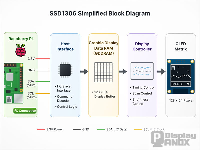
SSD1306 Simplified Block Diagram
SSD1306 modules are popular because they combine the display controller, display RAM, oscillator, contrast control, and interface functions in a compact device. The controller supports serial communication, while common breakout boards expose either I²C, SPI, or configurable interfaces.
For Raspberry Pi projects, the main advantages are straightforward:
-
A 128 × 64 display provides enough space for several lines of system information.
-
I²C uses only two communication lines in addition to power and ground.
-
Python libraries can render text, shapes, icons, and simple animations.
-
The module remains readable without occupying an HDMI port.
-
Power consumption is suitable for compact and battery-powered devices.
SSD1306 is not the only option. SH1106 modules are also common, while SSD1322 and SSD1327 support grayscale displays and SSD1331 or SSD1351 can drive small color OLED modules. The current Luma.OLED library supports a broad group of controllers, including SSD1305, SSD1306, SSD1309, SSD1315, SSD1316, SSD1322, SSD1325, SSD1327, SSD1331, SSD1351, SSD1362, SH1106, SH1107 and CH1115.
The controller model must be confirmed before software configuration. A module sold as a “1.3-inch OLED” may use SH1106 rather than SSD1306, even when its resolution and four-pin connector look almost identical.
I²C vs SPI for a Raspberry Pi OLED Display
Both interfaces work well for small OLED modules, but they suit different priorities.
I²C
An I²C module typically has four pins: VCC, GND, SDA, and SCL. It uses fewer GPIO connections and allows several devices to share the same bus, provided that their addresses do not conflict.
Its lower wiring complexity makes I²C the usual choice for clocks, environmental sensors, network status displays, and CPU monitors.
SPI
An SPI OLED normally exposes six or seven pins, including clock, data, chip select, data/command, and sometimes reset. It consumes more GPIO pins but offers faster data transfer.
SPI becomes more useful when the screen is refreshed frequently, when animations are required, or when a color OLED module transfers a larger framebuffer. Luma.OLED documentation notes that an I²C display commonly has four pins, while SPI modules normally have six or seven.
For a static 128 × 64 system monitor, I²C is usually the cleaner choice. For fast graphical updates, SPI provides more headroom.
How to Connect an SSD1306 I²C OLED to Raspberry Pi
The following example targets a Linux-based Raspberry Pi board, such as Raspberry Pi 3, 4, 5, or Zero. Raspberry Pi Pico is a microcontroller and uses a different MicroPython or CircuitPython workflow.
Required hardware
The basic setup requires:
-
A Raspberry Pi with a 40-pin GPIO header
-
An SSD1306-compatible I²C OLED module
-
Four female-to-female jumper wires
-
A suitable Raspberry Pi power supply
-
A microSD card running Raspberry Pi OS
Before wiring, the module datasheet or product page should be checked for its permitted supply voltage and pin order. Raspberry Pi GPIO signals operate at 3.3 V and are not 5 V tolerant.
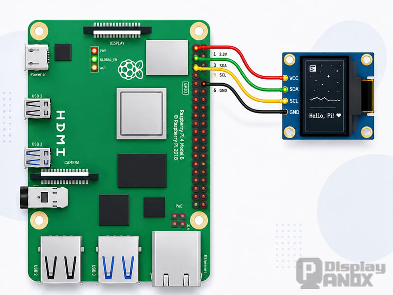
Typical I²C wiring
| OLED Pin | Raspberry Pi Connection | Physical Pin |
|---|---|---|
| GND | Ground | 6 |
| VCC | 3.3 V | 1 |
| SDA | GPIO 2 / SDA1 | 3 |
| SCL | GPIO 3 / SCL1 | 5 |
The order printed on the OLED board must be followed rather than assuming that every four-pin module uses the same layout. Reversing VCC and GND may permanently damage the display.
Some breakout boards include a regulator and accept a wider supply range. That does not make the Raspberry Pi GPIO lines 5 V tolerant. The module specification remains the final reference.
Enable I²C in Raspberry Pi OS
I²C can be enabled through the Raspberry Pi configuration tool:
sudo raspi-config
Navigate to:
Interface Options > I2C > Enable
Raspberry Pi’s current documentation states that enabling I²C activates the interface and loads the required kernel module at boot.
Install the I²C diagnostic tools:
sudo apt update
sudo apt install -y i2c-tools python3-venv
After wiring the display, scan the bus:
i2cdetect -y 1
A hexadecimal address in the grid confirms that an I²C device has responded. The address shown by this command should be used in the Python configuration instead of assuming a fixed value.
An empty grid usually points to disabled I²C, incorrect wiring, missing power, a damaged module, or a display configured for SPI rather than I²C.
Install the Luma.OLED Python Library
Older tutorials often install OLED libraries globally with sudo pip. That approach can conflict with the Python environment managed by newer Raspberry Pi OS releases.
The current Luma.OLED documentation recommends creating a virtual environment and installing the package inside it.
python3 -m venv ~/oled-env
~/oled-env/bin/python -m pip install --upgrade luma.oled
The environment can then be activated with:
source ~/oled-env/bin/activate
Luma.OLED is useful when a project may move between SSD1306, SH1106, grayscale, and small color OLED controllers. Adafruit’s CircuitPython SSD1306 library is another maintained option for SSD1306-specific applications on Linux-based Raspberry Pi systems.
Python Example: Display Raspberry Pi CPU Temperature
The following program reads the Linux thermal sensor and displays the current CPU temperature on a 128 × 64 SSD1306 OLED.
from pathlib import Path
from time import sleep

from luma.core.interface.serial import i2c
from luma.core.render import canvas
from luma.oled.device import ssd1306


OLED_ADDRESS = 0x3C
UPDATE_INTERVAL = 2


def read_cpu_temperature() -> float:
    thermal_file = Path("/sys/class/thermal/thermal_zone0/temp")
    raw_value = thermal_file.read_text(encoding="utf-8").strip()
    return int(raw_value) / 1000


serial = i2c(port=1, address=OLED_ADDRESS)
display = ssd1306(serial, width=128, height=64)

while True:
    try:
        temperature = read_cpu_temperature()

        with canvas(display) as draw:
            draw.text((0, 0), "Raspberry Pi", fill="white")
            draw.text((0, 22), f"CPU: {temperature:.1f} C", fill="white")
            draw.text((0, 44), "OLED online", fill="white")

        sleep(UPDATE_INTERVAL)

    except KeyboardInterrupt:
        display.clear()
        break

    except (OSError, ValueError) as error:
        print(f"Display update failed: {error}")
        sleep(UPDATE_INTERVAL)
If i2cdetect reports an address other than 0x3C, the OLED_ADDRESS value must be changed. A display with a different controller also requires a different device class. For example, an SH1106 module uses the sh1106 class rather than ssd1306.
The Luma drawing canvas is compatible with Pillow-style graphics operations, making it possible to add lines, rectangles, icons, custom fonts, scrolling text, and bitmap images.
Building a Raspberry Pi OLED System Monitor
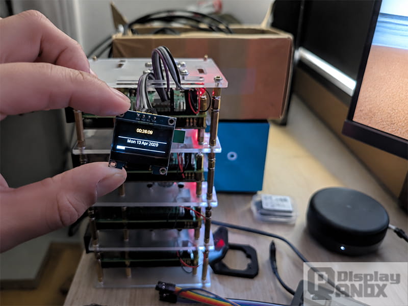
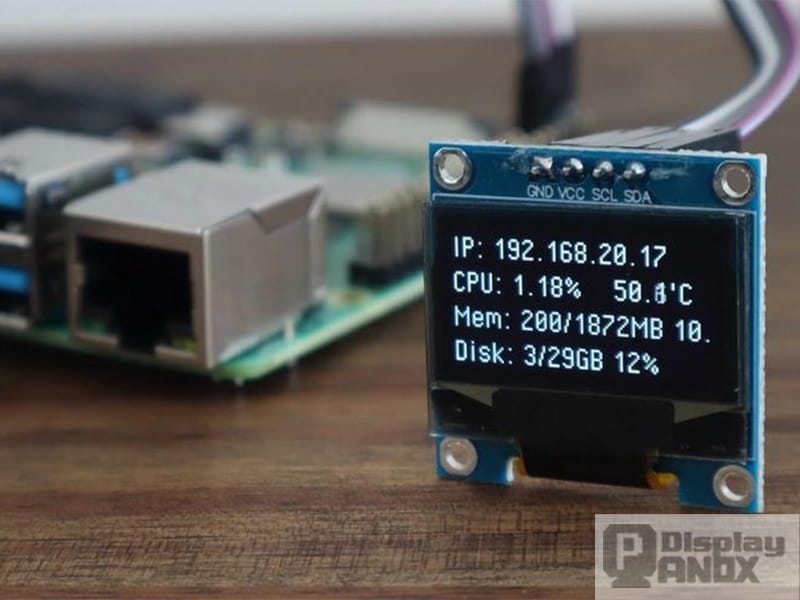
Raspberry Pi OLED module running in an embedded project
CPU temperature is only one useful value. A compact OLED dashboard can also show:
-
CPU load
-
RAM usage
-
Storage capacity
-
IP address
-
Network connection
-
Fan state
-
Sensor readings
-
Service or process status
A practical layout rotates between two or three pages rather than forcing every value onto a single 128 × 64 frame. A network page may show the IP address and connection state, while a hardware page displays temperature, load, and fan status.
Refresh timing also matters. System information rarely needs to update dozens of times per second. An interval of one to five seconds reduces unnecessary bus traffic and avoids visible instability.
Static OLED interfaces benefit from occasional page changes, reduced brightness, and a screen-off timeout. These measures also reduce the time that identical pixels remain continuously illuminated.
OLED Temperature Monitoring and Intelligent Fan Control
A Raspberry Pi OLED screen becomes more useful when it reports the state of a cooling system rather than only displaying a temperature number.
A typical design uses two thresholds:
-
The fan turns on when the CPU reaches an upper temperature limit.
-
The fan turns off only after the temperature falls below a lower limit.
This difference between the on and off thresholds is called hysteresis. It prevents the fan from rapidly switching near one temperature value.
Research on sustained visual inference workloads found that hysteresis-based active cooling prevented thermal throttling in the tested Raspberry Pi 4B scenarios and could substantially improve long-term throughput compared with operation without active cooling.
The fan must not be powered directly from a GPIO signal. A transistor or MOSFET driver stage should switch the fan supply, with component selection based on the fan voltage and current. Inductive loads may also require appropriate protection components.
The OLED can then display both temperature and cooling state:
CPU: 52.4 C
FAN: ON
LOAD: 67%
For unattended products, the software should also record errors, recover after an I²C communication failure, and start automatically through a systemd service.
Running the OLED Program at Startup
A systemd service provides a cleaner startup method than older /etc/init.d scripts.
Example service file:
[Unit]
Description=Raspberry Pi OLED System Monitor
After=multi-user.target

[Service]
Type=simple
User=pi
ExecStart=/home/pi/oled-env/bin/python /home/pi/oled-monitor.py
Restart=on-failure
RestartSec=5

[Install]
WantedBy=multi-user.target
Save the file as:
/etc/systemd/system/oled-monitor.service
Then reload and enable the service:
sudo systemctl daemon-reload
sudo systemctl enable oled-monitor.service
sudo systemctl start oled-monitor.service
Its status can be inspected with:
systemctl status oled-monitor.service
The user name and file paths must match the actual Raspberry Pi installation.
Common Raspberry Pi OLED Problems
The OLED does not appear in i2cdetect
The first checks are power, ground, SDA, and SCL. I²C must also be enabled in Raspberry Pi OS. If the module contains configurable solder bridges, its hardware interface may be set to SPI instead of I²C.
A second device on the same bus can also create an address conflict.
The screen is detected but remains blank
A successful I²C scan only confirms that a device responds on the bus. It does not confirm that the correct driver, resolution, or initialization sequence is being used.
The controller model should be verified. SSD1306 and SH1106 modules can look nearly identical but require different device classes.
The image is shifted or cropped
An incorrect resolution or controller definition often causes horizontal offsets, missing columns, or cropped content. The software width and height must match the physical panel.
Python installation fails
A virtual environment avoids most conflicts with the operating system’s managed Python packages. The application must then be launched with the Python interpreter inside that environment.
Text is too small or unreadable
The built-in font is suitable for testing but rarely suitable for a finished product. Pillow-compatible TrueType fonts provide better hierarchy and readability. Font size, line spacing, and page structure should be designed around the limited pixel grid.
The display flickers
Repeatedly clearing and redrawing the screen at a very high rate may create visible flicker. Other causes include unstable power, long jumper wires, electrical noise, or excessive I²C bus speed.
When an HDMI OLED Display Is the Better Choice
A small I²C OLED is designed for text, icons, and lightweight graphics. It is not a miniature replacement for a conventional monitor.
Applications that require a desktop interface, Chromium dashboard, video playback, camera preview, detailed charts, or touch interaction need a larger display with a video input path.
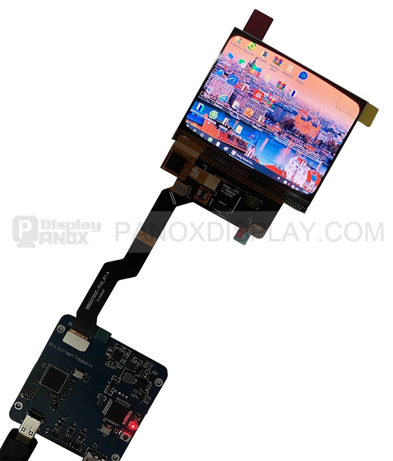
Many raw OLED and AMOLED panels expose MIPI DSI, RGB, LVDS, or eDP rather than HDMI. Raspberry Pi therefore cannot drive every panel through a simple cable. The panel timing, power sequence, interface standard, connector, firmware, and touch system must all be matched.
For these projects, Panox Display can pair an OLED or LCD panel with a custom OLED/LCD controller board. Available conversion architectures include HDMI to MIPI, HDMI to RGB, HDMI to LVDS, HDMI to eDP, and selected Type-C input solutions. Board shape, cable arrangement, firmware, brightness control, touch support, and other functions can be adapted to the display and enclosure.
This architecture allows Raspberry Pi to treat the screen as a conventional video display while the controller board handles the panel-specific interface.
How to Choose an OLED Display for Raspberry Pi
The selection process should begin with the required content rather than the screen size alone.
A small monochrome module is suitable when the interface contains a few changing values. I²C is preferable when wiring space is limited, while SPI is useful for faster updates.
A small color OLED may work for icons and compact graphical menus, but resolution, Python library support, and refresh performance should be checked before development begins.
A full-color OLED panel is more appropriate when the project needs Linux desktop output, video, complex UI elements, or touch. In this case, compatibility depends on the complete display system: panel, controller board, firmware, cables, power supply, and mechanical design.
The following specifications should be confirmed before ordering:
-
Active area and external dimensions
-
Resolution and aspect ratio
-
Native display interface
-
Controller or driver IC
-
Supply voltage and power sequence
-
Brightness and operating environment
-
Touch-panel type and touch controller
-
Cable orientation and connector position
-
Raspberry Pi model and intended video output
-
Required mounting and enclosure space
A display that matches the electrical interface but not the panel timing will still fail to produce an image. Panel part numbers and datasheets are therefore more reliable than generic marketplace descriptions.
Raspberry Pi OLED Screen Applications
Compact OLED modules are commonly used in network appliances, home automation hubs, sensor gateways, portable test equipment, audio players, clocks, and headless Raspberry Pi systems. They provide essential status information without requiring a full monitor.
Larger OLED panels support embedded HMIs, medical interfaces, portable media systems, smart-home terminals, industrial controllers, camera monitors, robotics, and product demonstrations.
The same Raspberry Pi can therefore support very different OLED architectures. A four-wire status module and a Full HD AMOLED panel solve different problems, even though both appear under the same search term.
Conclusion
A Raspberry Pi OLED screen should be selected as a complete display system, not only as a panel with a convenient size.
SSD1306 and SH1106 modules are effective for system status, sensor data, clocks, and compact embedded interfaces. Their I²C wiring is simple, Python support is mature, and a 128 × 64 display can present useful information without occupying an HDMI output.
Larger OLED and AMOLED panels serve a different role. They require a video signal path, matched timing, panel power control, firmware, and often an HDMI-to-MIPI, HDMI-to-LVDS, HDMI-to-RGB, or HDMI-to-eDP controller board.
Separating these two display categories prevents most compatibility problems and makes it easier to build a Raspberry Pi OLED solution that fits the intended interface, image content, enclosure, and operating environment.
Frequently Asked Questions
Can Raspberry Pi drive an OLED screen?
Yes. Small OLED modules can be driven through I²C or SPI using Python libraries. Larger OLED panels usually require HDMI, DSI, or a compatible controller board.
Is SSD1306 compatible with Raspberry Pi?
SSD1306 modules are widely used with Raspberry Pi. Compatibility depends on the module interface, supply voltage, resolution, and correct software configuration.
Is I²C or SPI better for an OLED display?
I²C requires fewer wires and is well suited to system information and sensor values. SPI offers faster transfer speeds and is more suitable for frequent graphical updates.
Why is the Raspberry Pi OLED screen blank?
Common causes include disabled I²C, incorrect wiring, an incorrect I²C address, the wrong controller class, mismatched resolution, unstable power, or a module configured for another interface.
Can an OLED panel connect directly to Raspberry Pi HDMI?
An OLED display with an integrated HDMI input can connect directly. A raw MIPI, LVDS, RGB, or eDP OLED panel requires a compatible controller board between the Raspberry Pi and the panel.
Can an OLED display show Raspberry Pi CPU temperature?
Yes. The temperature can be read from the Linux thermal interface or Raspberry Pi system tools and rendered on the OLED through a Python library such as Luma.OLED.



