







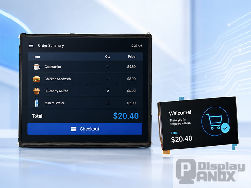
9.7 inch TFT-LCD and 5.5 inch Full Color OLED
In a POS terminal, the main screen and the secondary screen do not simply represent two pieces of glass mounted on the same device. From the system side, they are two display output paths that must be recognized, initialized, composed, and controlled correctly. The main screen is usually used by the cashier or operator for order entry, payment control, menu selection, inventory checking, and system settings, while the secondary screen is used for customer-facing information such as item details, total amount, QR payment status, advertisements, loyalty messages, or receipt prompts.
Many dual-screen POS projects first look like an application-layer problem: how to place one window on the main display and another window on the customer display. That is only the last step. If the lower display architecture is not prepared correctly, the application may only see a mirrored display, a black screen, an unstable output, or no secondary display at all. A real dual-screen POS display solution depends on three basic conditions: the hardware display pipeline must support independent output, the operating system must enumerate two displays, and the composition layer must be able to send different layers or framebuffers to different outputs.
This is why dual-screen POS development should start from display topology instead of UI layout. Before the cashier software, customer display page, or advertising module can work reliably, the display controller, connector, CRTC, panel driver, bridge chip, backlight, and Android or Linux graphics stack must all describe the same hardware reality.
1. Main and Secondary Screens in a POS Terminal
The main display of a POS terminal is designed for operation. It needs enough space for product lists, payment buttons, order modification, staff login, discount settings, and transaction records. In a compact Android POS device, a 7-inch high-resolution display can provide a good balance between size and UI clarity. In a larger desktop or countertop POS machine, a 9.7-inch display gives more room for multi-column layouts, menu grids, and order management.
For main-screen projects, Panox Display can recommend the 9.7 inch TFT-LCD 2048×1536 eDP Interface for larger operator-side terminals. Its QXGA resolution and 4:3 aspect ratio are suitable for dense POS interfaces, industrial-style control pages, retail checkout systems, and tablet-like terminals where the operator needs to read and manage more information on one screen. For more compact POS equipment, the 7.0 inch LCD Display 1200×1920 MIPI panel is another practical option. Its portrait resolution, LTPS TFT-LCD structure, MIPI interface, and controller board support make it useful for Android-based POS, handheld ordering devices, and space-limited embedded terminals.
The secondary screen has a different job. It does not need to copy the whole cashier interface. It should present clean, customer-facing information: item name, quantity, price, total amount, payment status, QR code, membership points, or a short promotion. For this position, a 5.5-inch display is often enough because the customer does not need the same operational density as the cashier. Panox Display’s 5.5 inch Full Color OLED 1920×1080 G1548 MIPI Touch Panel can be used when the secondary display needs vivid color, high contrast, on-cell touch, and a premium visual effect for payment confirmation or interactive customer prompts. The 5.5 inch LCD Display 1440×2560 MIPI panel is suitable for compact high-resolution customer displays, QR code screens, small payment modules, or secondary display projects that prefer LCD technology.
The important point is that screen selection should follow system architecture. A good display panel cannot solve a display pipeline problem by itself. If the SoC, driver, and operating system only expose one display path, the secondary screen may still become a mirror screen no matter how suitable the panel is.
2. The Display Driver Framework Behind Dual-Screen POS
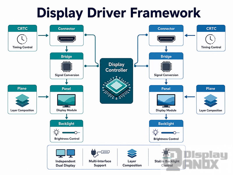
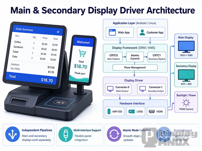
From the driver side, a dual-screen POS terminal is closer to “two display output paths” than “two screens.” In a Linux DRM/KMS architecture, the key objects usually include framebuffer, plane, CRTC, encoder, connector, bridge, panel, and backlight. The framebuffer stores image data, the plane carries display layers, the CRTC controls scanout timing, the encoder and connector describe the output path, and the panel or bridge driver sends the final signal to the real display module.
In actual POS hardware, the main and secondary display combination can be arranged in several ways. One common design uses MIPI DSI for the main display and HDMI for the customer display. Another design may use LVDS for both screens, or MIPI for the main panel and a bridge chip to convert the secondary output to LVDS or eDP. Some platforms allow the main and secondary screens to share the same display controller but use different CRTCs or output channels. The project can only support independent content when the display controller and system stack expose enough independent display resources.
If the hardware has only one scanout path and simply duplicates the signal to two panels, the operating system will usually treat it as one display. In that case, the application layer cannot naturally achieve independent main-screen and customer-screen content. The two panels may light up at the same time, but they will only behave like a mirror. On the other hand, even when the SoC supports two outputs, the secondary display may still fail if the device tree endpoint, panel driver, bridge driver, regulator, reset GPIO, or backlight node is not configured correctly.
For this reason, the first target of dual-screen bring-up is not to run the POS application. The first target is to make the display topology clear. The main connector should exist, the secondary connector should exist, every connector should bind to the correct encoder and CRTC, every panel should have its own timing and power sequence, and the composition layer should be able to send different framebuffers or layers to different displays.
3. Checking the DRM/KMS Display Pipeline
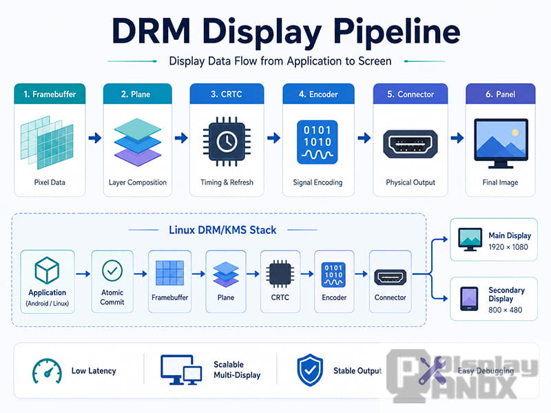
Linux DRM/KMS is useful in POS display development because it exposes the display chain in a relatively clear way. When debugging a main and secondary display system, it is better to check the connector and CRTC first instead of immediately looking at the UI. If the connector does not appear in the system, all application-layer debugging is basically built on sand.
A typical debugging process starts with tools such as modetest. Engineers can check whether the connector is connected, whether the expected display mode appears, whether the CRTC is assigned successfully, whether the plane supports the required pixel format, and whether atomic commit reports an error. These details are more useful than simply asking whether the screen is “black” or “not black,” because the same symptom can come from very different layers.
When the secondary display is HDMI, common problems include HPD, EDID reading, cable compatibility, and mode selection. When the secondary display is a MIPI, LVDS, RGB, or eDP panel, the problem is more often related to panel prepare and enable sequence, reset GPIO timing, regulator control, backlight enable, lane configuration, porch values, or pixel clock. A black screen does not always mean the application did not draw anything. It may mean the connector was never connected, the panel did not leave reset, the backlight did not turn on, or the atomic commit was rejected.
Driver debugging should also use kernel logs and DRM debug information when available. Dynamic DRM logs can help observe modeset and atomic commit behavior, while debugfs can show the current state of display objects. The purpose is not to memorize commands, but to build a layered judgment method: first confirm that the display object exists, then confirm that the mode is correct, then confirm that scanout is working, and only then move upward to the compositor and application.
4. Device Tree, Panel Driver, Bridge, and Backlight
In embedded Linux, many dual-display problems come from device tree and driver binding rather than the application layer. The display controller, ports, endpoints, panel, bridge, backlight, regulator, and GPIO nodes must describe a complete and correct route. If the display path is not described clearly, the DRM framework cannot assemble the full chain.
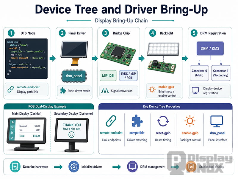
A typical display route includes a display controller node, one or more ports, remote endpoints, a bridge node if signal conversion is used, a panel node for timing and initialization, and a backlight node for LCD brightness control. The endpoint relationship is especially easy to get wrong in dual-display systems. A wrong port number, wrong remote-endpoint, wrong lane count, wrong bus format, or wrong data mapping can lead to a situation where the main screen works but the secondary screen does not appear, or where both screens appear in an unexpected order.
Probe order is another important detail. Panel, bridge, and display controller drivers may not probe at exactly the same time. A reliable DRM driver should handle probe defer correctly. If not, the secondary display may disappear randomly during boot, and the problem may look like an occasional hardware failure even though the root cause is driver registration timing.
The panel driver’s prepare and enable sequence also deserves careful attention. Power rails, reset timing, initialization delay, and backlight control must follow the panel specification. In a lab, a screen lighting up once may look like success. In a real POS terminal, that is not enough. The device will experience cold boot, repeated restart, suspend and resume, peripheral insertion, unstable power conditions, and long working hours. A display is only truly ready when it can return to the correct state every time.
5. Android POS: Kernel Display Output Is Only the First Step
Many modern POS terminals run Android, so the display driver must also connect correctly to the Android graphics stack. The application does not directly see the kernel connector. It sees a display that has been passed upward through Hardware Composer, SurfaceFlinger, and the Android framework.
The Android display path can be understood in layers. The kernel display driver controls the low-level output. Hardware Composer reports display capabilities and helps decide how layers should be composed. SurfaceFlinger manages and composes visible layers. DisplayManager and related framework APIs expose physical or logical displays to applications. For a POS customer-facing display, this means that two hardware outputs at the bottom do not automatically become two usable displays at the application level.
A common Android POS issue is that the secondary display is already connected in kernel logs, but the framework still does not show a usable presentation display. In this case, the focus should move to HWC hotplug reporting, display configuration, vsync handling, present fences, and display ID mapping. If the display appears in the Android display list but does not show content, the issue may be in layer composition, mode configuration, rotation, or present flow. If the secondary display becomes black after sleep and wake, suspend and resume handling, backlight restoration, and display disconnect or reconnect logic should be checked together.
For Android POS projects, the driver team and system team should define the secondary display behavior early. The project should decide whether the customer display supports hot-plug, whether it is fixed in portrait or landscape orientation, whether it has touch input, whether it can turn on and off independently, and whether it should keep showing advertisements when the main screen sleeps. These details affect not only the driver, but also HWC, framework policy, touch mapping, power management, and the POS application itself.
6. How to Separate Driver Problems from Application Problems
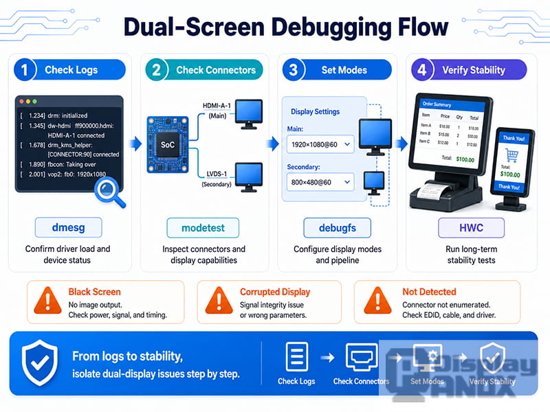
Dual-screen debugging becomes inefficient when every layer is discussed at the same time. A customer display black screen may involve hardware power, panel timing, bridge configuration, DRM connector state, Android HWC, SurfaceFlinger, UI window placement, or the POS application. If these layers are not separated, the team can spend a lot of time changing UI code while the real problem is still in the display pipeline.
A more reliable method is to prove one layer at a time. The first layer is hardware: power rails, reset signal, enable pin, PWM waveform, and backlight behavior should match the panel requirements. The second layer is kernel enumeration: connector, mode, panel, bridge, and backlight should be registered correctly. The third layer is direct display output: use KMS or platform test tools to output a test image without relying on the POS application. The fourth layer is the compositor: on Android, check HWC, SurfaceFlinger, and DisplayManager; on Linux desktop systems, check Wayland, X11, Qt, or the custom compositor. The final layer is application content distribution.
This order is important because it prevents false conclusions. If a direct KMS test can make the secondary display show a test pattern, the lower display path is probably usable, and the next investigation can move to the composition layer or application layer. If the KMS test cannot output anything, it is better to return to connector, CRTC, panel, bridge, timing, and backlight instead of continuing to modify the UI.
7. Stability Requirements for Commercial POS Devices
A POS terminal is a commercial field device, so “the screen lights up” is only a very early milestone. The display must stay reliable during real business use. A customer-facing black screen may interrupt payment confirmation, and a main-screen display issue can directly affect transaction flow. This makes stability more important than a one-time successful demo.
Dual-screen POS testing should cover cold boot, repeated restart, suspend and resume, secondary display recovery, HDMI hot-plug if used, different resolution combinations, portrait and landscape rotation, touch coordinate mapping, backlight control, long-time aging, static payment pages, advertisement playback, QR code readability, and busy transaction scenarios. If the secondary screen is used for payment status, the system must avoid showing stale QR codes, frozen order amounts, or outdated transaction messages after a reconnect or wake-up event.
Resolution mismatch is another practical detail. The main screen may be a 9.7-inch 2048×1536 LCD, while the secondary display may be a 5.5-inch 1920×1080 OLED or a 1440×2560 LCD. The compositor and application layout should handle these differences instead of assuming that both screens share the same size, orientation, or pixel density. If a portrait display is mounted horizontally in the enclosure, rotation and touch mapping must be handled in a predictable layer of the system.
8. Display Panel Selection for Main and Customer-Facing POS Screens
Display selection should follow both user experience and driver architecture. For the operator side, the main display needs enough resolution, stable viewing angle, suitable touch integration, and a mechanical size that matches the terminal structure. The 9.7 inch TFT-LCD 2048×1536 eDP Interface can be considered for larger POS terminals that need more visible information on the main screen. The 7.0 inch LCD Display 1200×1920 MIPI panel is more suitable for compact Android POS terminals, handheld ordering devices, and smaller desktop systems where a sharp portrait display is needed.
For the customer-facing side, the display should be clear rather than crowded. A 5.5-inch OLED screen can make payment status, QR code, membership information, and brand visuals look more vivid, especially when high contrast and wide viewing angle are important. Panox Display’s 5.5 inch Full Color OLED 1920×1080 G1548 MIPI Touch Panel also supports on-cell touch, which is useful when the secondary screen needs simple interaction such as digital receipt selection, loyalty confirmation, or customer consent. The 5.5 inch LCD Display 1440×2560 MIPI panel is a good fit for compact secondary LCD modules that need very sharp text, QR code display, or portrait customer information pages.
However, the selected panel should always be checked together with the display interface, controller board, cable route, power sequence, backlight design, driver support, and operating system environment. Panox Display can support display module selection, datasheet supply, connector and adapter board support, customized touch panel, controller board consultation, and display testing advice for embedded POS development.
9. Engineering Recommendations for Dual-Screen POS Development
A reliable dual-screen POS display project should be planned from the schematic stage. The hardware team should confirm whether the SoC truly supports independent dual-display output instead of simple hardware mirroring. The display interface should be chosen according to mechanical structure, signal distance, resolution, operating system, and board layout. If a bridge chip is used, its initialization, power sequence, and driver support should be included in the early design review.
During device tree and driver development, the main and secondary display paths should be described separately. Their ports, endpoints, panel nodes, bridge nodes, regulators, reset GPIOs, and backlight nodes should not be mixed casually. The driver should handle probe defer, prepare and enable, disable and unprepare, suspend and resume, and error recovery in a complete way. During system integration, Linux DRM/KMS or Android HWC should expose both displays clearly to the upper layer. During production validation, the team should build display tests for boot, sleep, wake-up, hot-plug, brightness, resolution, rotation, and long-time operation.
The application experience of a main and secondary POS display is built on the driver topology. When the lower layer exposes two stable display paths, the upper layer can safely implement cashier operation, customer-facing order confirmation, QR payment, promotion playback, and payment result synchronization. When the lower display pipeline is unstable, the application can only keep chasing symptoms.
Conclusion
Main and secondary display output in POS equipment is a system-level problem. The user sees a simple result: one screen for the cashier and one screen for the customer. Behind that result, the hardware display controller, DRM/KMS topology, panel and bridge drivers, device tree configuration, Android HWC, SurfaceFlinger, display framework, and application layer must all work together.
For manufacturers developing dual-screen POS terminals, the most important step is to confirm independent display capability early. The project should not wait until the application stage to discover that the secondary display can only mirror the main screen. Once the display pipeline is planned correctly, suitable panels such as a 9.7-inch high-resolution LCD, a 7-inch MIPI LCD, a 5.5-inch OLED touch panel, or a 5.5-inch 2K LCD can be selected according to the product structure and user scenario.
A stable dual-screen POS display does more than show two images. It separates operator workflow from customer communication, improves transaction transparency, supports payment confirmation, and gives the whole POS terminal a more professional experience from both sides of the counter.



