







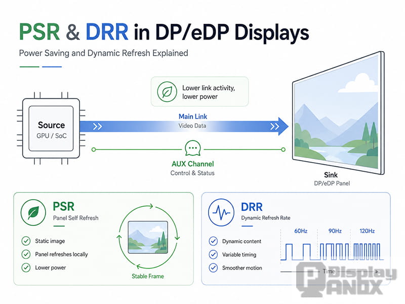
In display driver development, power saving and smooth motion often meet on the same DP or eDP link. The source side decides how video data is sent. The sink side decides how the panel receives, stores and refreshes that data. The panel may need to maintain a static image by itself, while the system may also need to change refresh behavior when content becomes dynamic.
That is where Panel Self Refresh and Dynamic Refresh Rate become important. In DP and eDP projects, Panel Self Refresh is usually referred to as PSR. Dynamic refresh behavior may appear as DRR, VRR, Adaptive-Sync or a platform-specific policy. These terms are often discussed together because they all reduce unnecessary display activity, but they are not the same feature.
PSR is mainly about static content. When the image does not change, the sink can keep the current frame locally, allowing the source to reduce or stop continuous pixel transmission. DRR and VRR are mainly about dynamic content. They allow the refresh cadence or frame interval to follow the content more closely, reducing wasted refreshes, repeated frames and visible stutter.
For embedded display products, especially laptops, tablets, industrial displays, handheld devices, automotive HMIs and portable instruments, this distinction is not just theoretical. It affects panel selection, driver tuning, power validation and long-term stability.
PSR and DRR Solve Different Problems
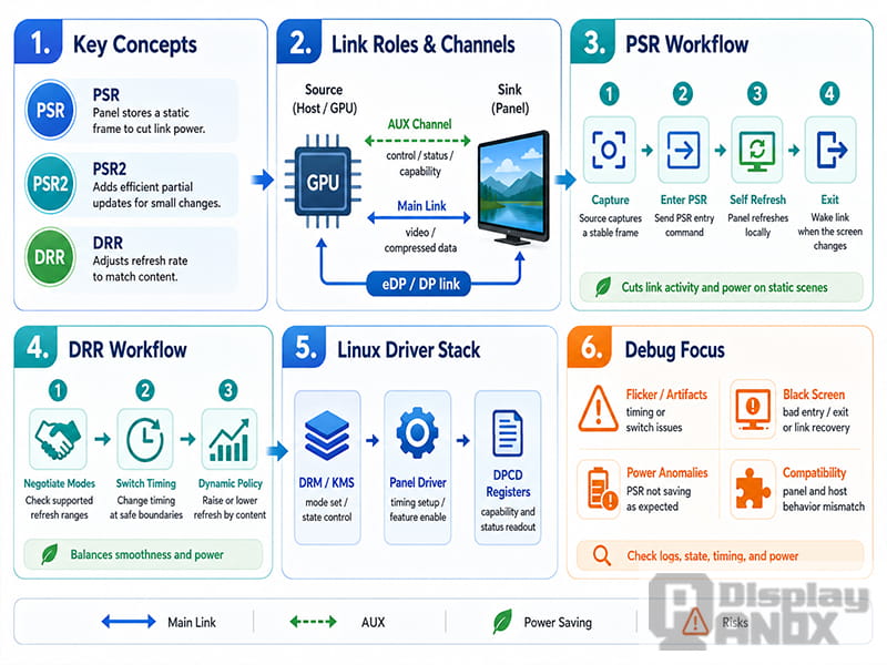
A DP/eDP display path usually includes four important parts: the source, the sink, the Main Link and the AUX channel. The source is typically a GPU, display controller or SoC display pipeline. The sink is the panel side, usually a TCON, bridge IC or integrated display module. The Main Link carries pixel data, while the AUX channel is used for capability discovery, register access and status communication.
PSR and DRR both depend on these parts, but they change different layers of behavior.
Panel Self Refresh focuses on the question: when the screen is static, can the panel maintain the image without the source continuously sending the same frame?
Dynamic Refresh Rate focuses on a different question: when the screen is changing, can the refresh rhythm match the actual content instead of forcing every scene into one fixed refresh rate?
This difference is useful during debugging. When the screen content is static but system power does not drop, the first area to check is usually PSR entry, exit and state tracking. When scrolling, animation, gaming or video playback feels unstable during refresh changes, the investigation should move toward DRR, VRR, mode timing and VBlank boundaries.
PSR is a link power-saving state machine. DRR is a refresh timing strategy. Mixing them together too early makes display bugs look more mysterious than they really are.
What Panel Self Refresh Does
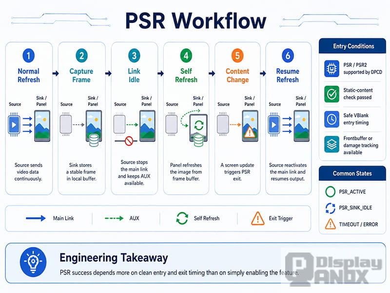
Panel Self Refresh allows the panel to refresh a static image from its own local frame buffer. The source first drives the panel normally. Once the frame is stable, the sink captures the image. Then the source can allow the sink to enter self-refresh mode through AUX communication. During this state, the Main Link can enter a lower-power condition because the panel no longer needs the same pixels to be sent repeatedly.
The power benefit can come from several places. The display link may remain quiet for longer periods. The display controller may reduce activity. System memory reads may also be reduced because the source does not need to fetch and send the same framebuffer again and again. In battery-powered products, these savings can be meaningful during reading, idle desktop use, document viewing or standby-like screen-on scenarios.
The basic PSR flow sounds simple, but production issues usually appear around two decisions: when the image is stable enough to enter PSR, and when the system must exit PSR.
If PSR enters too aggressively, users may see flicker, dirty blocks, cursor delay or short black frames. If PSR exits too conservatively, the display may fail to update quickly when the framebuffer changes. If PSR exits too often, the feature may be enabled on paper but provide little real power saving.
This is why PSR tuning is rarely about one enable bit. It involves frontbuffer tracking, plane updates, cursor paths, CRC behavior, atomic commits, VBlank timing and panel-side state handling. A driver can expose PSR support correctly and still behave poorly if the surrounding display pipeline does not track changes accurately.
PSR2 extends the idea with more efficient partial or selective updates. Instead of treating every small change as a reason to refresh the entire frame, PSR2 can update only the region that changed. This is useful for modern interfaces where the screen is almost static but not perfectly still, such as a blinking cursor, a moving pointer, a small notification or a limited UI update.
For Linux-based platforms, a practical first step is to enable DRM/KMS logs and observe whether PSR enters and exits as expected.
# Enable DRM/KMS logs to observe PSR entry and exit behavior
sudo sh -c 'echo 0x1ff > /sys/module/drm/parameters/debug'

# debugfs paths vary by platform; list connector and PSR-related nodes first
sudo find /sys/kernel/debug/dri -maxdepth 3 -iname '*psr*' -o -iname '*connector*'

# Monitor kernel logs for link training, frontbuffer activity, and PSR state changes
sudo dmesg -w | grep -Ei 'psr|edp|dp|frontbuffer|vblank'
A useful PSR investigation can be divided into three layers.
The first layer is capability. The sink must declare PSR or PSR2 support correctly through DPCD, and the panel firmware must behave according to that claim. A specification table alone is not enough. Some panel SKUs require platform-specific restrictions, firmware updates or driver quirks.
The second layer is state. The driver must meet the entry conditions and avoid being interrupted constantly by plane updates, cursor movement, CRC checks, atomic commits or frontbuffer activity. Many PSR failures are not caused by the panel itself, but by a display pipeline that keeps invalidating the self-refresh state.
The third layer is symptom. Flicker, black screen, dirty region, cursor delay and slow wake-up usually point to different causes. Treating every PSR issue as the same problem wastes time. The exit path and timing boundary must be matched to the actual visual symptom.
For eDP internal panels, PSR can provide attractive power savings, but it is also sensitive to panel compatibility. The same SoC may behave differently when the panel SKU changes. In mass production projects, it is common to maintain panel-specific parameters, platform quirks, allowlists or blocklists.
Dynamic Refresh Rate Is a Timing Policy
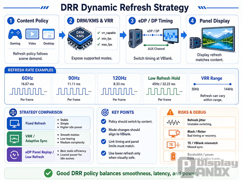
Dynamic Refresh Rate is sometimes simplified as “switching from 60 Hz to 120 Hz” or “dropping to 30 Hz when idle.” In real driver work, the topic is broader. The system must know what frame rate the application or compositor wants, which display modes the panel supports, whether the switch must happen at a VBlank boundary, whether the pixel clock changes, whether the link bandwidth needs to be recalculated, and whether the user can notice the transition.
In a Linux graphics stack, refresh rate policy is usually not decided by the display driver alone. The compositor, DRM/KMS driver, panel driver, bridge IC driver, firmware and power management policy can all participate. The driver side must expose accurate connector properties, execute atomic commits safely, keep link training reliable and switch timing without causing visible instability.
DRR, VRR and Adaptive-Sync are related, but their usage depends on platform context. DRR is often used to describe system-managed refresh rate switching. VRR is commonly used for variable refresh behavior where the frame interval can change dynamically. Adaptive-Sync refers to the VESA technology that allows variable refresh operation over DisplayPort and eDP when the source and sink support the required behavior.
The goal is not simply to use a lower refresh rate. The goal is to use the right refresh behavior for the scene. A static document should not force the display pipeline to run at maximum refresh all the time. A 24 fps video should not need unnecessary repeated frames if the display path can match the content cleanly. A game or interactive UI should not tear or stutter because the rendered frame rate and display refresh are fighting each other.
For applications that prioritize smoother motion, lower perceived latency, or high-frame-rate visual performance, related panel options can be explored under the High Refresh Rate display category.
Before changing driver code, tools such as modetest and trace-cmd can help confirm connector modes, properties and timing behavior.
# Check connector, mode, and property information, including whether vrr_capable is exposed
modetest -M rockchip

# On other platforms, the DRM driver name may be i915, amdgpu, msm, mediatek, or another driver
modetest -M i915

# Trace atomic commits and page flip timing to locate refresh-rate switching boundaries
sudo trace-cmd record -e drm -e power -e irq sleep 10
Most DRR risks appear during transitions. A refresh rate change may affect pixel clock, M/N values, link rate, lane count, porch timing or blanking intervals. If the switch happens at the wrong moment, the result may be judder, tearing, flicker or a short black screen.
Policy oscillation is another common issue. A system that keeps jumping between 60 Hz, 90 Hz and 120 Hz may not save much power, and users may feel that the display is unstable. A good dynamic refresh policy should consider the scene, not just the numerical refresh rate.
Panel compatibility must also be tested carefully. A panel may list multiple supported refresh rates, but some combinations of resolution, color depth, DSC, link rate, blanking timing and power state may be less stable than others. For commercial products, it is not enough to prove that one refresh rate can be selected once. The system must switch repeatedly and safely under real workloads.
Debugging PSR and DRR: Capability First, Registers Later
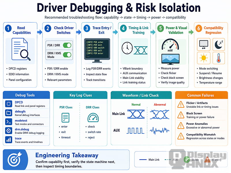
PSR and DRR debugging should not begin with random register changes. A safer order is to confirm capability first, then observe state behavior, and only then inspect timing boundaries, link training and power results.
Capability checks include DPCD, EDID, panel descriptors, device tree or ACPI configuration, firmware restrictions and driver quirks. If the sink does not expose the required capability correctly, the driver should not force the feature.
State checks confirm whether the system enters, holds and exits the expected state. For PSR, the key signals are often frontbuffer tracking, cursor movement, plane updates and atomic commits. For DRR or VRR, the more important signals are connector properties, mode timing, page flips, VBlank intervals and link behavior.
Timing checks focus on the transition itself. Many display bugs do not appear during a stable state. They appear when the panel exits PSR, changes refresh cadence, wakes from a low-power state, resumes after suspend or switches between content types.
When the platform supports direct DPCD access, the driver should read sink capability before enabling PSR behavior. The following simplified example shows the logic. It is not intended to be a complete production driver.
/* Read sink capability first, then decide whether the feature should be enabled */
static bool panel_supports_psr(struct drm_dp_aux *aux)
{
    u8 val = 0;
    int ret;

    /* Use the DPCD address defined by the platform headers; this example only shows the read flow */
    ret = drm_dp_dpcd_read(aux, DP_PSR_SUPPORT, &val, sizeof(val));
    if (ret < 0)
        return false; /* Do not force PSR on when AUX access fails */

    return val & DP_PSR_IS_SUPPORTED;
}
In actual projects, the validation plan should cover five areas: capability reading, driver enablement, state observation, visual behavior and power measurement.
Capability reading confirms whether DPCD, EDID, panel description and platform configuration agree with one another. Driver enablement confirms whether kernel parameters, Kconfig options, platform quirks and connector properties are working. State observation checks debugfs, dmesg and traces to see whether the feature enters, stays active and exits as expected.
Visual testing should cover static desktop, cursor movement, touch input, video playback, brightness changes, screen on/off, suspend/resume and wake-up. Power validation is equally important. PSR and DRR are usually enabled to save power, so the benefit should appear on the relevant system rails. If the display looks correct but power does not improve, the feature may be exiting too often or another part of the display subsystem may still be active.
A practical rule is to debug PSR by asking whether exit is timely and clean. Debug DRR by asking whether refresh switching is stable and invisible. PSR problems are often tied to frontbuffer, cursor, plane update and panel self-refresh state. DRR problems are often tied to mode timing, VBlank, link training and compositor policy.
How PSR and DRR Interact in Real Products
PSR and DRR are both valuable, but neither should be enabled as aggressively as possible without product-level validation. Different devices have different priorities.
A tablet may need both long battery life and smooth touch scrolling. A notebook may prioritize idle power saving during reading and office work. An industrial display may value stability more than aggressive refresh changes. An automotive HMI may need strict behavior across temperature, power transitions and long operating time.
The best approach is to validate features in stages. First, create a capability matrix for each panel, refresh rate, link rate, lane count, color depth and system power state. Then validate PSR and DRR separately. After the basic paths are stable, enable them together and look for interactions between self-refresh entry, refresh-rate switching and power transitions.
Real usage scenes are more useful than perfect test images. A static desktop may pass easily, while touch scrolling reveals timing problems. A video loop may look fine, while suspend/resume causes a black screen. A panel may pass at room temperature but become unstable at the edge of its operating range.
This is especially important when the display system includes a bridge IC, external TCON, touch controller, backlight driver or custom power sequence. These components can change the behavior of what looks like a simple DP/eDP panel connection.
What This Means for DP/eDP Display Panel Selection
For display panel selection, interface type alone is not enough. A panel described as eDP may still differ greatly in refresh support, PSR behavior, timing tolerance, link bandwidth, power sequence and firmware maturity.
When a product requires Panel Self Refresh, Dynamic Refresh Rate, VRR or Adaptive-Sync behavior, the panel should be evaluated together with the source platform and driver stack. The source must support the feature. The sink must expose the right capabilities. The driver must implement the state machine correctly. The panel must remain visually stable across real workloads.
Panoxdisplay supports display selection and customization for embedded applications where interface behavior, power consumption and visual stability matter. For DP and eDP display projects, the evaluation should include resolution, refresh rate, color depth, link rate, lane count, backlight requirements, touch integration, mechanical structure and operating environment.
A successful display project does not start with the highest specification number. It starts with a panel and system combination that can work reliably in the final product. For PSR and DRR, that means checking not only whether the feature is listed, but whether it can be enabled, measured, switched and recovered safely.
Conclusion
Panel Self Refresh and Dynamic Refresh Rate both help make display systems more efficient, but they work in different ways.
PSR answers the static-image question: when the screen is not changing, can the panel maintain the frame locally so the source and link can reduce activity?
DRR, VRR and Adaptive-Sync answer the dynamic-content question: when the screen is changing, can the refresh cadence follow the content more intelligently?
Once this boundary is clear, DP/eDP debugging becomes easier to organize. PSR issues can be traced through capability, frontbuffer tracking, entry and exit behavior. DRR issues can be traced through mode timing, VBlank, link training and refresh policy. With proper validation, these features can improve both power efficiency and user experience without turning the display pipeline into a source of flicker, black screens or unstable refresh behavior.
For embedded display products, the most reliable strategy is to treat PSR and DRR as system-level features rather than panel-only checkboxes. The panel, source controller, driver, firmware and product workload must be validated together. That is the path toward a stable, power-efficient and production-ready DP/eDP display solution.
Learn more: High Refresh Rate Monitor and Display Panels: What Refresh Rate Really Means for Modern Visual Devices



