







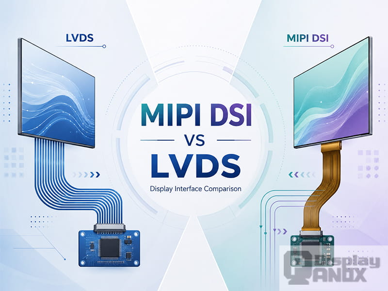
Display interface selection has a direct impact on image quality, PCB routing, connector design, power consumption, EMI performance, and the overall difficulty of bringing up a display module. Among embedded LCD and OLED projects, MIPI DSI and LVDS are two of the most common display interfaces, but they are often confused because both are high-speed serial interfaces and both use differential signaling in many implementations.
The difference is not only about speed. LVDS is mainly a physical signaling technology widely used to transmit RGB video data and timing signals from a host board to a display panel. MIPI DSI is a display interface protocol designed for communication between a processor and a display module. It can carry pixel data, control commands, configuration packets, and display status communication depending on the panel and host design.
For engineers selecting a TFT LCD, AMOLED, Micro OLED, or embedded display module, understanding this difference helps avoid wrong connector choices, incompatible driver boards, missing initialization codes, and unnecessary redesigns.
What Is LVDS in Display Panels?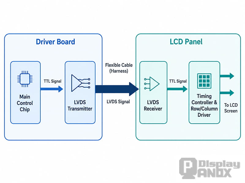
Schematic Diagram of an LVDS Interface Circuit
LVDS stands for Low-Voltage Differential Signaling. In display applications, the term usually refers to an LVDS-based flat panel interface such as OpenLDI, FPD-Link, or similar RGB-to-LVDS transmission formats. The host side serializes parallel RGB data, sync signals, data enable, and pixel clock into differential pairs. The panel side then receives the serialized data and converts it back into the timing signals required by the display driver circuit.
This structure made LVDS popular in laptop displays, industrial LCD panels, medical displays, POS terminals, automotive screens, and many medium-to-large embedded displays. Compared with traditional parallel RGB TTL interfaces, LVDS reduces the number of wires, improves noise immunity, and supports more reliable transmission across board-to-panel cables.
A typical LVDS display link includes several data pairs and one clock pair. For example, many single-pixel 18-bit or 24-bit LVDS panels use three or four data pairs plus one clock pair. Higher-resolution or dual-pixel designs may use more lanes. The exact mapping must match the panel specification, especially when the datasheet refers to JEIDA, VESA, Format 1, Format 2, 6-bit, 8-bit, single-channel, or dual-channel LVDS.
LVDS is mature and stable, but it is not a command-rich display interface by itself. Most LVDS panels expect a continuous video stream. Panel configuration, backlight control, touch communication, or power sequencing is usually handled by separate lines such as I2C, SPI, PWM, enable pins, or dedicated control circuits.
What Is MIPI DSI?
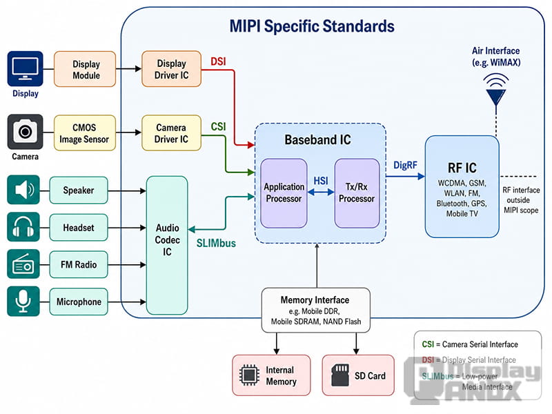
MIPI DSI, short for MIPI Display Serial Interface, is a high-speed serial display interface developed for connecting host processors to display modules. It is widely used in smartphones, tablets, wearables, VR/AR devices, embedded systems, smart meters, industrial handhelds, and compact high-resolution display products.
Unlike LVDS, MIPI DSI is not just a simple serialized RGB video link. It defines how display data and commands are packetized, transmitted, and interpreted. A MIPI DSI display normally uses a physical layer such as MIPI D-PHY, with one clock lane and one or more data lanes in many common implementations. The number of data lanes depends on the resolution, refresh rate, color depth, host capability, and panel design.
MIPI DSI can work in video mode or command mode. In video mode, the host continuously streams pixel data to the display, which is common for many LCD panels and embedded Linux systems. In command mode, the host sends display commands and pixel updates in packets, often used when the display module includes local display memory or when lower power operation is important.
This command capability is one of the biggest differences between MIPI DSI and LVDS. MIPI DSI can send initialization commands, sleep-in and sleep-out commands, brightness settings, display on/off commands, gamma-related settings, tearing effect control, and other panel-specific instructions. In real projects, a MIPI DSI panel may not show any image even if the hardware wiring is correct, simply because the initialization sequence, lane configuration, or D-PHY timing is not properly set.
MIPI DSI vs LVDS: The Core Difference
The simplest way to understand the difference is this: LVDS display interfaces are mainly designed to transport video timing and RGB pixel data, while MIPI DSI is designed to transport display data through a packet-based protocol that can also include control commands.
| Item | LVDS Display Interface | MIPI DSI Display Interface |
|---|---|---|
| Main role | Transmits RGB video data and timing signals | Transmits video data, commands, and display control packets |
| Common signal structure | Differential data pairs plus clock pair | One clock lane and multiple data lanes in D-PHY designs |
| Data style | Serialized RGB timing stream | Packet-based protocol with video and command modes |
| Control capability | Usually requires separate control lines | Supports display commands through DSI/DCS-type communication |
| Typical use | Industrial LCDs, laptops, medical equipment, POS, automotive displays | Smartphones, tablets, wearables, VR/AR, compact embedded displays |
| Bring-up focus | Pixel clock, timing, mapping, channel format, cable quality | Initialization code, lane count, D-PHY settings, video/command mode, timing |
| Connector impact | Fewer pins than parallel RGB, but usually more than MIPI DSI | Very low pin count for high-resolution compact modules |
| Compatibility | Depends on LVDS channel count and mapping | Depends on DSI lane count, mode, command set, and host driver support |
Both interfaces can support high-quality displays, but they are not directly interchangeable. A MIPI DSI host cannot drive an LVDS panel without a bridge IC, and an LVDS output cannot directly drive a MIPI DSI panel. Even when a bridge board exists, the bridge must match resolution, timing, color format, lane configuration, voltage, firmware, and panel initialization requirements.
Signal and Protocol Differences
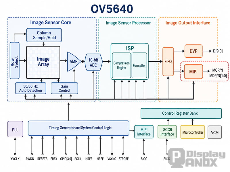
Internal Functional Block Diagram of a MIPI-Interfaced SENSOR
LVDS is often easier to understand from a hardware perspective. The host generates RGB data, horizontal sync, vertical sync, data enable, and pixel clock. These signals are serialized into LVDS pairs and sent to the display. As long as the voltage, channel mapping, clock, timing, and cable design are correct, the panel usually behaves like a video receiver.
MIPI DSI adds more layers. The host does not simply send raw RGB lines across wires. It packages display information into DSI packets and sends them through a high-speed physical layer. During bring-up, the host may need to reset the panel, enter low-power command transmission, send vendor-specific initialization commands, configure the panel, and then switch to video streaming or command updates.
This is why two displays with the same resolution and connector pitch can still behave very differently. An LVDS panel mainly asks whether the host can output the right timing and mapping. A MIPI DSI panel asks whether the host can support the right lane count, D-PHY data rate, video mode or command mode, pixel format, and initialization sequence.
Bandwidth, Pin Count, and PCB Layout
MIPI DSI is often preferred when a compact product needs high resolution, slim wiring, and low pin count. It is especially suitable for smartphones, handheld devices, wearable displays, near-eye displays, and thin embedded products where connector space is limited. A 2-lane or 4-lane MIPI DSI connection can carry a large amount of display data with fewer physical pins than a comparable parallel RGB or many LVDS designs.
LVDS remains attractive when the display is larger, the platform already provides LVDS output, or the project needs a stable and widely supported interface for industrial equipment. LVDS links are also familiar to many hardware teams because the timing model is close to RGB display output. For products using existing industrial motherboards, single-board computers, or legacy display controllers, LVDS can reduce software complexity.
PCB layout matters for both interfaces. Differential impedance, length matching, return path continuity, connector quality, and cable shielding can all affect signal integrity. MIPI DSI generally has stricter requirements for lane configuration and high-speed signal behavior, while LVDS designs often pay close attention to channel mapping, pair skew, cable length, and EMI around the clock pair.
Power and EMI Considerations
Both LVDS and MIPI DSI were developed to improve high-speed signal transmission compared with wide parallel buses. LVDS uses low-voltage differential transmission to reduce noise and EMI while maintaining reliable data transfer. This is one reason it has stayed popular in industrial and professional display systems.
MIPI DSI also aims for low power and low EMI, but it approaches the problem through a protocol and physical-layer design optimized for mobile and embedded products. MIPI D-PHY supports high-speed data transmission and low-power states, which helps reduce power consumption when the display does not need continuous high-bandwidth activity. In battery-powered devices, this can be important.
The better choice depends on the system. A compact device with a modern application processor may benefit from MIPI DSI. A powered industrial product using a long-established LCD controller may be more practical with LVDS. Power consumption should always be evaluated at the full system level, including the display panel, backlight or OLED driving power, bridge ICs, cables, and host processor workload.
Software and Bring-Up Complexity
LVDS display bring-up is usually centered on timing. The key questions are whether the resolution, pixel clock, horizontal and vertical porch values, sync polarity, data enable signal, color depth, and LVDS mapping are correct. If the image appears with wrong colors, shifted position, flicker, or no display output, the issue is often related to mapping, timing, clock, cable direction, or power sequencing.
MIPI DSI bring-up is more software-dependent. The hardware may be correct, but the panel can still remain black if the initialization command table is missing or incomplete. Many MIPI DSI panels require vendor-specific commands that are not obvious from the connector definition alone. The host driver must also match the panel’s video mode or command mode, lane number, data rate, color format, TE signal behavior, reset timing, and power sequence.
For this reason, MIPI DSI panels are best selected together with host platform information. Before choosing a display, it is important to confirm whether the processor, SoC, MCU, bridge board, or driver IC already supports the target panel configuration.
When to Choose LVDS
LVDS is often a good choice for industrial displays, medical equipment, test instruments, POS systems, rugged tablets, machine vision terminals, automotive display subsystems, and embedded products that need a stable video interface with mature hardware support.
It is especially practical when the host board already provides LVDS output, when the display size is medium or large, or when the system does not need complex display-side command control. Many industrial LCD modules are designed around LVDS because it offers a balanced combination of signal integrity, cable tolerance, availability, and long-term platform support.
LVDS is also easier to integrate in projects where software resources are limited. Once the correct timing and mapping are configured, the interface behaves predictably. That makes it a strong option for many long-life B2B products.
When to Choose MIPI DSI
MIPI DSI is usually the better option when the product needs a compact connector, high pixel density, thin mechanical design, lower pin count, or a display module commonly used in mobile-style platforms. It is widely used in AMOLED modules, high-resolution TFT LCDs, wearable screens, smart home panels, portable instruments, VR/AR displays, and other compact embedded systems.
MIPI DSI is also useful when the display requires command-based control. Brightness setting, sleep mode, display inversion, refresh control, and panel initialization can be handled through the DSI command path. This gives the system more control, but it also means that the software stack must be prepared before mass production.
A MIPI DSI display should not be chosen only because the connector looks small or the resolution looks attractive. The host interface, driver support, command table, lane count, and power sequence must be checked at the same time.
Can MIPI DSI and LVDS Be Converted?
MIPI DSI and LVDS can be converted through bridge ICs or adapter boards, but conversion is not a simple cable change. A bridge must translate protocol, timing, pixel format, and electrical signaling. In a MIPI-to-LVDS design, the bridge receives DSI packets and outputs LVDS video timing. In an LVDS-to-MIPI design, the bridge must accept LVDS video data and generate a DSI-compatible output for the target panel.
Bridge solutions are useful when the host and display panel do not share the same native interface, but they add cost, PCB area, power consumption, firmware work, and another point of failure. For production projects, a native interface match is usually cleaner unless there is a strong reason to use a bridge.
PanoxDisplay Display Interface Support
PanoxDisplay provides LCD, AMOLED, OLED, Micro OLED, and custom display modules with interface options such as MIPI DSI, LVDS, RGB, SPI, MCU, HDMI adapter boards, and other embedded display solutions. For new projects, interface selection should be reviewed together with resolution, display size, brightness, refresh rate, touch panel structure, operating temperature, mechanical outline, and host platform.
For a compact handheld or wearable device, MIPI DSI may help reduce connector size and support modern high-resolution modules. For industrial equipment or larger TFT LCD applications, LVDS may offer easier timing control and stronger compatibility with existing controller boards. When the host platform is already fixed, the best display is not always the highest-spec panel, but the panel that can be electrically, mechanically, and software-wise integrated with the lowest risk.
Conclusion
MIPI DSI and LVDS are both important display interfaces, but they solve different design problems. LVDS is a reliable video transmission interface based on low-voltage differential signaling and is widely used in industrial and embedded LCD systems. MIPI DSI is a packet-based display interface that supports both video data and display control commands, making it well suited for compact, high-resolution, and mobile-style products.
The right choice depends on the display panel, host processor, PCB layout, software driver, product size, power target, and production risk. Before selecting a display module, engineers should confirm not only the resolution and connector, but also the interface type, lane count, timing, command requirements, power sequence, and long-term supply plan.
For projects that require a suitable LCD, AMOLED, or Micro OLED display module, PanoxDisplay can help evaluate whether MIPI DSI, LVDS, or another interface is the better fit for the final product design.
Learn more: MIPI DSI Interface Guide: Protocol, D-PHY, Linux Driver Bring-Up, and Debugging



