







1. What Is MIPI DSI?
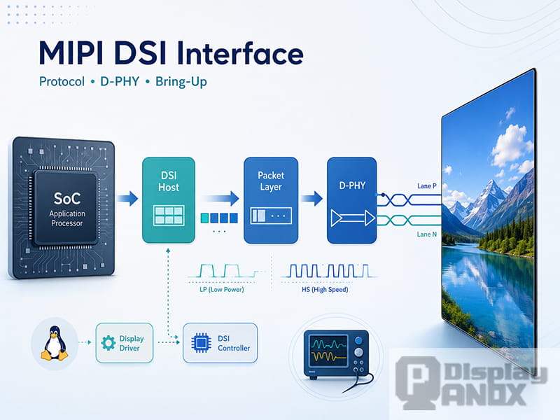
MIPI DSI, short for Mobile Industry Processor Interface Display Serial Interface, is a high-speed serial display interface used to connect a host processor to a display module. It is widely used in smartphones, tablets, handheld devices, AR/VR products, wearables, industrial terminals, medical equipment, and other embedded display systems where compact wiring, high bandwidth, and low power consumption matter.
In a display system, MIPI DSI usually sits near the end of the visual pipeline. The application processor or SoC prepares the image data, the display controller or DRM/KMS pipeline manages timing and composition, the DSI host packages the data, the physical layer converts it into high-speed electrical signals, and the panel driver IC finally interprets the data and lights up the pixels.
This is why MIPI DSI integration is rarely just a "software setting" or a "hardware connection" problem. A stable MIPI DSI display depends on the protocol configuration, D-PHY signal quality, panel initialization sequence, power timing, reset control, pixel format, lane count, driver binding, and long-term reliability testing. If only one part is checked, a black screen or flickering display can easily be misjudged as a defective panel.
At Panox Display, MIPI DSI is treated as a complete display link rather than a single connector type. The real engineering task is to make the display panel, host platform, initialization commands, PCB routing, and system software work as one verified path.
2. Where MIPI DSI Fits in a Display System
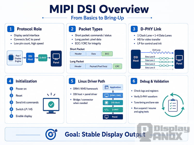
A typical embedded display path can be understood in several layers.
The upper layer is the application or graphical interface. It may be an Android UI, Linux framebuffer application, Qt interface, HMI software, or a custom rendering system.
Below that is the display framework. In Linux systems, this often involves DRM/KMS, display controllers, planes, CRTCs, encoders, bridges, connectors, and panel drivers. In MCU or RTOS systems the path may be more direct, but the same basic questions remain: what resolution is being output, what pixel format is used, what timing is required, and how the panel receives commands.
The MIPI DSI host then converts display data and control commands into DSI packets. These packets are transmitted through the physical layer, usually MIPI D-PHY. The panel driver IC receives the packets, applies the initialization settings, and drives the LCD, OLED, AMOLED, or Micro OLED display.
A simplified display chain looks like this:
Application / UI → Display controller or DRM/KMS pipeline → MIPI DSI host → MIPI D-PHY lanes → Display driver IC → Panel pixels and backlight or self-emissive display
This layered view is useful during debugging. A no-display issue before the DSI host is usually different from a D-PHY signal problem. A wrong gamma table is different from a wrong lane rate. A backlight timing mistake is different from a failed panel initialization command. Treating the whole path as one chain makes failures easier to isolate.
3. MIPI DSI Protocol Basics: Packets, Commands, and Pixel Data
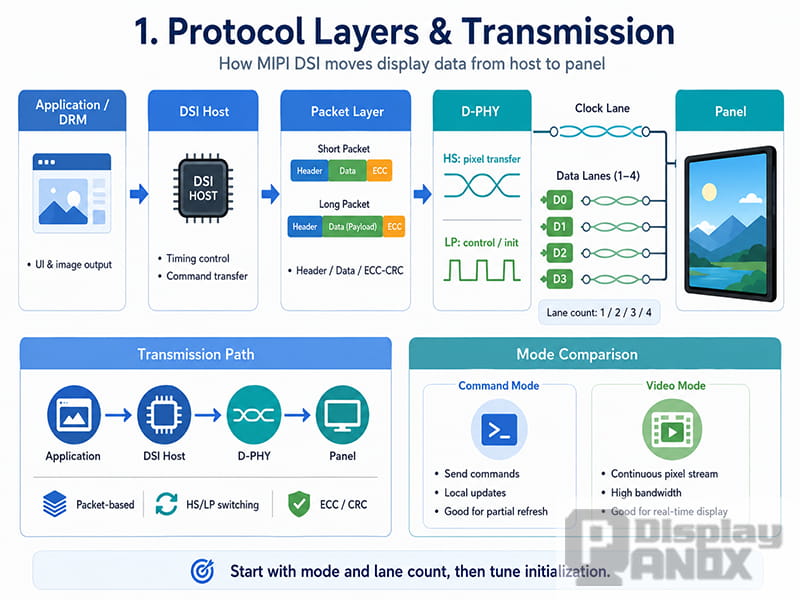
MIPI DSI is a packet-based display protocol. Instead of sending only raw parallel RGB signals, the host sends structured packets that carry commands, parameters, synchronization information, or pixel data.
In practical display bring-up, two packet categories matter most: short packets and long packets.
Short packets are commonly used for control commands, synchronization events, and small amounts of data. They are often involved in operations such as sleep out, display on, tearing-effect control, address setting, or status readback.
Long packets are used when more data must be transferred. Pixel data, larger parameter tables, and continuous display content are usually transmitted in long packet form. Long packets include payload data and error-checking fields, so link stability and timing margin become important when resolution or refresh rate increases.
A MIPI DSI display issue is not always caused by the wrong command. A command table may be correct, but the panel can still show noise, color shift, flickering, or random black screens if the lane rate is too aggressive, the D-PHY signal margin is weak, the porch timing is wrong, or the LP-to-HS transition is unstable.
This is one of the main differences between reading a datasheet and completing a real display bring-up. The datasheet gives the required parameters, but the system must still prove that those parameters are transmitted correctly under real electrical, thermal, and software conditions.
4. Command Mode vs Video Mode
MIPI DSI displays are commonly discussed through two operating modes: command mode and video mode. They are not just abstract protocol terms — they directly affect bandwidth, refresh behavior, power consumption, driver structure, and debugging methods.
4.1 MIPI DSI Command Mode
Command mode is closer to the way many MCU-style displays work. The host sends commands and data to the display module, and the panel driver IC may store image data in its internal GRAM or framebuffer. This mode is often used for displays that support partial refresh, low-power UI updates, or static images.
It can be useful in wearable devices, handheld instruments, smart home panels, and small OLED or TFT displays where the screen content does not need to be refreshed continuously at a high frame rate. It reduces unnecessary data transmission when only part of the image changes.
During command mode debugging, the focus is usually on command reliability, panel response, DCS commands, manufacturer command tables, delay timing, TE signal behavior, and readback support. If the display stays black after initialization, check sleep-out timing, display-on timing, reset status, and command transmission mode carefully.
4.2 MIPI DSI Video Mode
Video mode is closer to traditional RGB display timing. The host continuously sends pixel data according to the configured resolution, refresh rate, sync width, back porch, front porch, and pixel format. This mode is common for high-refresh displays, real-time video, larger LCD panels, and systems where the panel expects a steady stream of image data.
Video mode places more pressure on bandwidth calculation and timing accuracy. Resolution, frame rate, bits per pixel, lane count, and protocol overhead must all be considered. A panel may light up in the lab but become unstable in mass production if the lane rate runs too close to the physical limit.
For video mode debugging, the key checks include pixel clock, lane rate, horizontal and vertical timing, sync configuration, DSI mode flags, burst or non-burst behavior, and the relationship between the display controller and the DSI host.
The choice of mode also shapes the driver path and the tools you reach for. A simplified view:
enum dsi_mode {
    DSI_MODE_CMD,   // command mode: register config, partial refresh, panels with GRAM
    DSI_MODE_VIDEO, // video mode: continuous pixel stream
};

static int dsi_select_mode(enum dsi_mode mode)
{
    if (mode == DSI_MODE_CMD) {
        // during init, prioritize reliable command delivery
        return DSI_LP_CMD_TRANSFER;
    }

    // normal refresh runs at high speed; bandwidth and lane params must match
    return DSI_HS_VIDEO_TRANSFER;
}
A simple engineering rule: command mode problems often start with initialization and control flow, while video mode problems often involve continuous timing, bandwidth, and signal margin.
5. MIPI D-PHY: The Physical Layer Behind DSI
MIPI DSI commonly runs over MIPI D-PHY, the physical layer that converts packet data into electrical signals. A standard D-PHY display connection usually includes one clock lane and one to four data lanes, depending on resolution, refresh rate, color depth, and bandwidth requirement.
The clock lane provides the timing reference, while the data lanes carry the display information. In many embedded displays a 1-lane DSI interface may be enough for small low-resolution panels; a 2-lane or 4-lane interface is more common for higher resolution, higher refresh rate, or higher color depth products.
D-PHY supports two major signaling states: high-speed (HS) mode and low-power (LP) mode. Low-power mode is usually used for control transactions, initialization commands, and state changes. High-speed mode is used for large data transfers, especially continuous pixel data in video mode.
This HS/LP switching behavior is one of the reasons MIPI DSI debugging can be tricky. A system may look correct in software logs, but the actual D-PHY waveform may show unstable lane transitions, weak signal amplitude, timing violations, or impedance problems. The panel does not care whether the software configuration looks elegant; it only responds to the electrical signals that arrive at its receiver.
Common D-PHY-related issues include incorrect lane count configuration, lane order mismatch, lane rate set too high, poor differential pair routing, impedance discontinuity, excessive length mismatch, weak grounding or power noise, connector or FPC signal degradation, unstable LP-to-HS or HS-to-LP transitions, and marginal performance at temperature extremes.
For compact display modules — especially small high-resolution OLED, AMOLED, and Micro OLED panels — D-PHY signal quality often decides whether the display is merely "able to light up" or truly ready for production.
6. From Datasheet to Display Bring-Up
A MIPI DSI panel datasheet usually provides much more than resolution and connector pinout. For a reliable bring-up, the following must be aligned between the panel, host platform, schematic, PCB, and driver: resolution and active area, MIPI lane count, pixel format (RGB565, RGB666, or RGB888), command or video mode, DSI mode flags, horizontal and vertical porch values, sync width, refresh rate, lane rate or clock requirement, power rails and voltage tolerance, reset pin behavior, the initialization command table, required delays after power/reset/sleep-out/display-on, backlight or OLED enable timing, TE signal requirement if used, and operating temperature and reliability conditions.
The usual mistake is to copy the command table but ignore timing and electrical details. A panel may need a specific delay after reset before it can accept commands. Some driver ICs require sleep-out and display-on commands to be separated by a fixed delay. Some panels need the power rails to ramp in a certain order. Some modules are sensitive to reset pulse width.
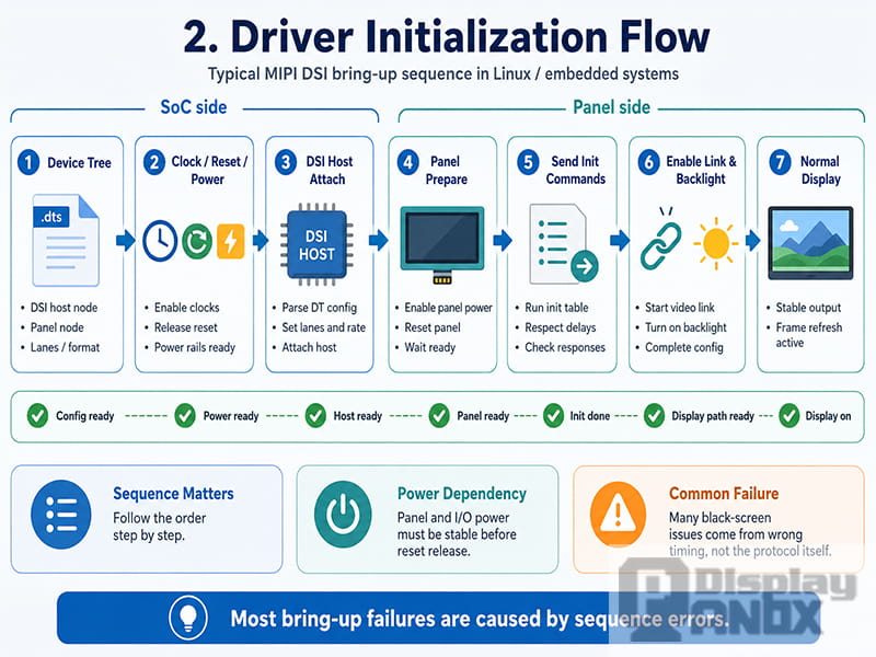
A good bring-up starts with a clean, observable sequence: enable the required power rails; hold or release reset according to the panel timing; prepare the DSI host clock and lane configuration; attach the DSI device to the host; send initialization commands in the required mode; wait for the required delays after critical commands; enable video transmission or frame update; turn on the backlight or panel emission; then verify image, color, timing, and stability.
static int panel_prepare(struct panel_ctx *ctx)
{
    int ret;

    // power first, so the panel isn't at an undefined level when reset releases
    ret = regulator_enable(ctx->vdd);
    if (ret)
        return ret;

    // release reset per the datasheet timing; don't casually trim these delays
    gpiod_set_value(ctx->reset_gpio, 0);
    msleep(20);
    gpiod_set_value(ctx->reset_gpio, 1);
    msleep(120);

    // check return values per command block, so you can see which command stalls
    ret = dsi_write_table(ctx, init_cmds, ARRAY_SIZE(init_cmds));
    if (ret)
        return ret;

    // prepare done means the panel is ready; backlight comes on after enable
    ctx->prepared = true;
    return 0;
}
This sequence sounds simple, but many black-screen issues hide inside it. If the backlight turns on before the panel is ready, the user may see a white screen or flash. If the DSI host enters high-speed transmission before the panel exits reset properly, the software may not report a clear error. If an initialization delay is too short, the display may work at room temperature and fail in the cold.
7. Linux DRM/KMS and MIPI DSI Panel Drivers
On Linux-based platforms, MIPI DSI integration usually involves the DRM/KMS display framework. The exact structure depends on the SoC vendor, kernel version, bridge IC, panel type, and device tree design, but the main components are often similar.
The DSI host driver manages the MIPI DSI controller on the SoC — host registration, packet transmission, lane configuration, and interaction with the display pipeline. The panel driver describes the display module: panel timing, power sequence, reset control, initialization command table, prepare and enable callbacks, and the disable/unprepare flow. A bridge driver may appear between host and panel when the system uses a conversion chip such as MIPI DSI to LVDS or MIPI DSI to eDP. The connector represents the display sink in the DRM model; for fixed embedded panels it is not user-pluggable like HDMI, but the abstraction still matters for mode setting and pipeline binding.
In the Device Tree, several details must match both the hardware and the panel specification: the DSI host node must be correctly connected to the display controller; the panel node must use the correct compatible string; the number of data lanes must match the schematic and panel; the pixel format must match the panel driver IC; mode flags must match command/video mode, burst behavior, and sync requirements; reset GPIO, enable GPIO, power supply, and backlight nodes must match the board; and the display timing must match the datasheet.
A practical Linux bring-up log should make each step visible. Instead of only printing "panel prepare failed," a better driver separates power enable, reset release, DSI attach, command-table transmission, panel enable, and backlight enable. This makes field debugging much faster.
A typical debugging flow starts with the system-side evidence:
# display / panel / DSI host logs — confirm driver binding and where errors appear
dmesg | grep -Ei "drm|dsi|panel|mipi|backlight"

# DRM connector and mode info — confirm the active resolution and refresh rate
cat /sys/kernel/debug/dri/0/state

# raise DRM log verbosity to keep more link detail while reproducing the issue
echo 0x1ff > /sys/module/drm/parameters/debug
The exact debug command may vary with kernel configuration and platform, but the goal is the same: capture the point where the display path fails instead of guessing blindly.
8. Bandwidth and Lane Rate Calculation
For MIPI DSI video mode, bandwidth should be calculated before hardware and driver decisions are finalized. The basic raw bandwidth can be estimated from resolution, refresh rate, and bits per pixel:
Raw pixel bandwidth = horizontal pixels × vertical pixels × refresh rate × bits per pixel
This value then needs to be adjusted for blanking intervals, DSI packet overhead, physical-layer margin, and platform-specific requirements, and the result is divided across the available data lanes.
For example, a higher-resolution display with RGB888 color at 60 Hz requires much more bandwidth than a small RGB565 command-mode display. If the system only has one or two DSI lanes available, the lane rate may become too high. In that case the project may need a lower refresh rate, a different pixel format, more lanes, compression support, or a different interface strategy.
Bandwidth should not be designed with zero margin. A display that works only when the lane rate is pushed to the edge may fail during temperature cycling, EMI testing, cable variation, or production tolerance changes. Stable display design is about margin, not just a successful first light-up — and for high-resolution AMOLED, Micro OLED, AR/VR near-eye displays, and compact industrial panels, that margin matters most, because the module may be physically small while the interface demand stays very high.
9. Common MIPI DSI Display Problems and How to Approach Them
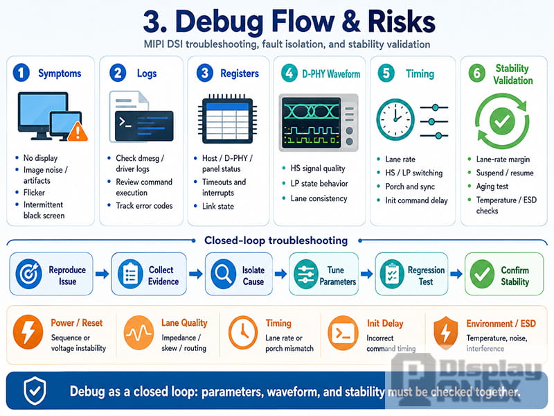
MIPI DSI debugging is more efficient when symptoms are grouped before parameters are changed. Randomly editing porch values, lane rates, or command tables often creates more confusion.
No display. A completely black screen can come from power, reset, command transmission, DSI host binding, a wrong compatible string, a missing backlight, or incorrect lane configuration. The first step is to separate "panel not initialized" from "panel initialized but not displaying video." Useful checks: power rail measurement, reset waveform, driver probe log, DSI attach result, initialization command return value, and backlight enable timing.
White screen or backlight only. A white screen often means the backlight is on while the panel is not correctly initialized or not receiving valid pixel data — the backlight enabled too early, the panel stuck in reset, a failed init table, or an inactive video stream. The backlight should normally be enabled only after the panel is prepared and output is active.
Flickering display. Flickering may come from unstable power, incorrect refresh timing, TE mismatch, porch configuration error, insufficient D-PHY margin, or a command/video mode mismatch. If it appears only at certain temperatures or after long operation, check power stability and signal margin closely.
Random black screen. These are often harder than fixed failures. Possible causes include ESD events, power dips, marginal lane rate, an unstable clock lane, sleep/wake sequence problems, or driver state recovery failure. Repeated suspend/resume testing and long-duration aging tests are useful here.
Color error or image shift. Wrong colors may come from an incorrect pixel format, RGB/BGR order, endian setting, color coding, or panel register configuration. Image shift may come from wrong porch values, sync width, active area, or scan direction settings.
Noise, lines, or screen tearing. Noise and random lines can point to D-PHY signal quality, PCB routing, connector quality, lane mismatch, or bandwidth margin. Tearing may relate to TE signal configuration, partial refresh strategy, or a mismatch between frame update timing and display scan timing.
In all cases, avoid changing five things at once. Change one parameter, record the result, and keep logs, waveforms, and visual symptoms connected.
10. D-PHY Signal Validation
Software logs are necessary, but they do not prove signal integrity. When a project reaches production validation or repeated instability, D-PHY measurement becomes important. The main checks: whether the clock lane is stable; whether all data lanes enter high-speed mode correctly; whether LP-11, LP-to-HS, and HS-to-LP transitions behave as expected; whether the differential signal amplitude is within margin; whether lane skew is acceptable; whether the eye diagram has enough opening; whether impedance and termination are correct; and whether the waveform changes under temperature, cable movement, or power variation.
A display may pass a simple power-on test but still fail during ESD, aging, temperature cycling, or EMI testing. For products such as industrial HMI, medical equipment, automotive-related displays, outdoor handheld terminals, and AR/VR devices, that difference matters. The target is not only to light up the panel, but to keep it stable in the final application.
11. Practical Design Notes for MIPI DSI Display Modules
Several decisions should be made before a custom MIPI DSI project enters layout or software development.
First, confirm whether the host platform supports the required lane count, lane rate, pixel format, and display mode. Some SoCs support MIPI DSI in theory but have limits in actual driver availability or clock configuration.
Second, confirm whether the panel needs command mode, video mode, or a specific hybrid behavior. A driver IC may support multiple modes, but the module supplier's recommended initialization sequence should be followed.
Third, check the FPC pinout and board routing early. MIPI DSI uses high-speed differential signaling, so connector selection, impedance control, pair matching, layer stack-up, and grounding should be handled carefully.
Fourth, define the power and reset sequence clearly. The delay values in the panel specification should not be removed just to make boot faster — many display failures appear only after repeated power cycles or cold starts.
Fifth, make the software driver observable. A driver that logs each major step is much easier to debug than one that hides the entire bring-up inside a single command table.
Finally, verify the display under real use conditions. A panel that works on a desk may behave differently inside a sealed enclosure, under battery voltage drop, near wireless modules, or at the edge of its temperature range.
12. How Panox Display Supports MIPI DSI Projects
Panox Display provides display modules and customization support for projects that need compact, high-resolution, application-ready display solutions. MIPI DSI is often selected when a product needs a slim FPC connection, reduced pin count, high image bandwidth, and compatibility with modern application processors.
For MIPI DSI projects, Panox Display can support panel selection, interface confirmation, resolution matching, brightness and viewing evaluation, touch integration, FPC customization, backlight design, and basic bring-up reference information. For projects using LCD, AMOLED, OLED, or Micro OLED panels, early confirmation of the host platform and display timing reduces integration risk.
The most successful MIPI DSI projects usually start with a clear specification package: target display size and resolution; host processor or development board; required interface lane count; operating system or firmware environment; expected brightness and viewing condition; touch panel requirement; mechanical space and FPC direction; operating temperature range; and production volume and reliability requirement.
With these details, the display module can be selected and adapted with fewer unknowns. For embedded products, this saves time not only during the first sample test, but also during PCB design, driver integration, and production validation.
13. Conclusion
MIPI DSI is often described as a mobile display interface, but in real product development it is much more than a connector name. It is a complete display link that combines packet protocol, D-PHY signaling, panel initialization, host driver configuration, PCB design, and reliability testing.
A reliable MIPI DSI bring-up should answer several questions clearly. Are the lane count, pixel format, and mode flags correct? Are the initialization commands sent in the right order with the required delays? Does the DSI host attach properly to the panel or bridge? Is the backlight enabled only after the panel is ready? Does the D-PHY waveform confirm stable LP and HS behavior? Can the display survive repeated power cycles, suspend/resume tests, temperature changes, and long-term operation?
When these questions are verified as one engineering chain, MIPI DSI becomes easier to manage. It is no longer a set of mysterious registers or fragile command tables. It becomes a structured display interface that can be designed, measured, debugged, and maintained for real products — from compact modules and high-resolution panels to AR/VR near-eye displays, industrial terminals, handheld devices, and custom embedded systems.
Learn more: How to Bring Up a MIPI DSI Display: A Practical Guide for Embedded Display Integration



