







Bringing up a MIPI DSI display is rarely just a matter of writing one driver function or sending one initialization command. A MIPI display module sits at the intersection of hardware power design, reset timing, DSI Host configuration, PHY parameters, panel initialization commands, backlight control, Linux DRM/KMS display pipeline, and the final image source from the application layer.
This is why many MIPI DSI display issues appear similar at first. A black screen may come from an incorrect reset sequence, a missing backlight node, a failed DSI attach, an incomplete panel driver, or a DRM pipeline that never becomes active. A flickering or distorted image may look like a panel defect, while the actual cause may be an incorrect pixel format, lane rate, porch timing, or video mode setting.
For embedded product teams, the reliable way to light up a MIPI display is to treat the process as a complete signal chain rather than a single software task. Each part of the chain should be checked, measured, and confirmed before moving to the next step.
Panox Display works with MIPI LCD, AMOLED, OLED, and Micro OLED modules for different embedded applications, including handheld devices, AR/VR systems, industrial terminals, medical instruments, smart devices, and custom display solutions. This article explains a practical MIPI DSI display bring-up workflow from an engineering perspective.
1. What Makes MIPI DSI Display Bring-Up Different?
MIPI DSI, short for Mobile Industry Processor Interface Display Serial Interface, is a high-speed serial display interface widely used between host processors and display modules. Compared with RGB, SPI, LVDS, or parallel display interfaces, MIPI DSI reduces pin count and supports high-resolution, high-refresh-rate display transmission in a compact form factor.
However, MIPI DSI panels are not usually “passive” displays that only need pixel data. Most MIPI DSI panels contain a display controller IC. Before the panel can show an image, the host processor must wake the panel, configure internal registers, exit sleep mode, turn the display on, and then send video data or command-based image updates in the correct mode.
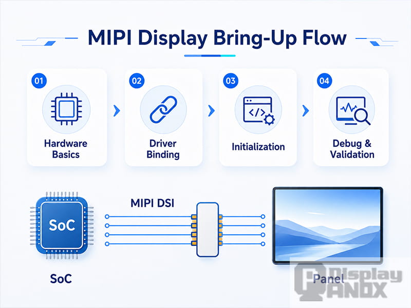
A typical MIPI DSI display bring-up process includes:
-
Supplying the correct power rails, such as AVDD, IOVCC, VCI, VDD, or other panel-specific voltages
-
Applying the reset signal according to the panel datasheet
-
Configuring the DSI Host and D-PHY
-
Setting the correct number of data lanes
-
Selecting the pixel format, such as RGB888, RGB666, or RGB565
-
Choosing video mode or command mode
-
Sending the panel initialization sequence
-
Executing standard DCS commands such as Sleep Out and Display On
-
Enabling the DRM/KMS display pipeline
-
Turning on the backlight or display brightness control
-
Confirming that image buffers are actually reaching the display pipeline
Missing only one of these steps may result in a black screen. Getting one of them slightly wrong may produce flicker, color shift, unstable startup, or random failure after suspend and resume.
2. Understand the Display Chain Before Debugging
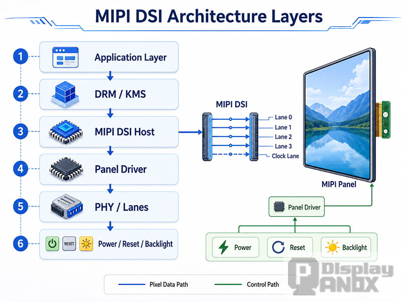
A MIPI DSI display project should be divided into two paths: the pixel path and the control path.
The pixel path is responsible for moving image data from the processor to the panel. It includes the display controller, DRM/KMS pipeline, DSI Host, PHY, lane configuration, bit clock, pixel format, resolution, refresh rate, and display timing.
The control path is responsible for preparing the panel to receive and show that image data. It includes regulators, reset GPIO, enable GPIO, DCS commands, vendor-specific initialization commands, sleep mode control, display-on commands, and backlight control.
These two paths are connected, but they should not be debugged as one blurry problem. A system may already be sending pixel data correctly while the panel remains in sleep mode. Another system may have a correct initialization sequence but no active display pipeline. In some cases, the backlight is simply not enabled, making a working display look dead.
A practical MIPI DSI bring-up workflow should always separate these questions:
-
Is the panel powered correctly?
-
Is the reset signal correct?
-
Is the DSI Host attached to the panel?
-
Is the panel initialization sequence executed?
-
Is the panel out of sleep mode?
-
Is the display-on command sent?
-
Is the backlight enabled?
-
Is the DRM/KMS pipeline active?
-
Is the application layer submitting real image buffers?
-
Are the DSI timing, lane count, and pixel format correct?
This separation makes troubleshooting much faster and avoids random parameter changes that may introduce new problems.
3. Start with Hardware: Power, Reset, Backlight, and Lane Connection
Before changing driver code, the hardware conditions must be verified. Many MIPI DSI display failures are caused by power sequencing, reset polarity, backlight control, or lane routing, not by the panel driver itself.
3.1 Check the Power Rails
MIPI display modules often require multiple power rails. The names vary by panel and controller IC, but common rails may include logic voltage, analog voltage, I/O voltage, OLED driving voltage, or backlight power.
The first step is to compare the schematic with the panel specification. The actual voltage should be measured on the board, not only assumed from the device tree or PMIC configuration.
Important checks include:
-
Whether each required power rail is present
-
Whether the voltage level matches the panel datasheet
-
Whether the power-up sequence follows the recommended order
-
Whether the power rail is stable during panel initialization
-
Whether the voltage drops when the backlight turns on
-
Whether the panel power is controlled by a regulator, GPIO, PMIC, or always-on rail
A panel may probe successfully in Linux even if the hardware power is not correct. Probe success only means that the software object exists. It does not prove that the physical panel is ready to operate.
3.2 Verify Reset Timing
Reset timing is one of the most common causes of MIPI display bring-up failure. The reset pin may be active high or active low, and the required delay may differ from one panel controller to another.
A correct reset sequence usually includes:
-
Power rails enabled first
-
Reset asserted for the required minimum time
-
Reset released
-
A stabilization delay before sending commands
-
Additional delay after Sleep Out before Display On
If the reset delay is too short, the panel may ignore initialization commands. If the reset polarity is wrong, the panel may remain in reset while the driver continues as if the panel were ready.
For reliable projects, reset should be checked with an oscilloscope during boot. Kernel logs alone cannot confirm the physical waveform.
3.3 Confirm Backlight Control
For LCD modules, a black screen does not always mean that the display interface has failed. If the backlight is not enabled, the panel may already be showing an image that is simply not visible.
Backlight control may use:
-
PWM brightness control
-
Enable GPIO
-
Constant-current LED driver
-
I2C backlight controller
-
Power rail controlled by PMIC or load switch
Typical backlight checks include:
-
Whether the backlight node exists in the device tree
-
Whether the PWM channel is correct
-
Whether the enable GPIO polarity is correct
-
Whether the brightness value is greater than zero
-
Whether the LED power rail is present
-
Whether the backlight turns on independently of image data
For OLED, AMOLED, and Micro OLED panels, there may not be a traditional LED backlight. Brightness is controlled through panel commands, power settings, gamma, emission control, or driver IC registers. In this case, the display-on sequence and brightness-related commands become even more important.
3.4 Check DSI Lane Count and Lane Order
A MIPI DSI display may use one, two, three, or four data lanes, plus a clock lane when using D-PHY. The number of lanes must match the panel, the processor, and the PCB routing.
Common lane-related issues include:
-
Device tree sets 4 lanes while the panel or board only uses 2 lanes
-
Lane order is swapped on the PCB
-
Lane polarity is not handled correctly
-
The DSI clock lane is active but data lanes are not
-
The selected lane rate is outside the stable range
-
Flexible cable or connector orientation is incorrect
Lane problems may cause complete black screen, random noise, unstable image, or failure only at higher refresh rates.
4. Device Tree: Describe the Hardware Chain Correctly
In Linux-based systems, the device tree is not just a way to make the driver probe. It describes how the display hardware is connected. A MIPI display node should clearly describe power supplies, reset GPIO, backlight, DSI connection, lane number, pixel format, and endpoint relationship.
A simplified panel node may look like this:
panel@0 {
    compatible = "vendor,example-mipi-panel";
    reg = <0>;

    reset-gpios = <&gpio3 12 GPIO_ACTIVE_LOW>;
    vdd-supply = <&vcc_lcd>;
    backlight = <&backlight>;

    port {
        panel_in: endpoint {
            remote-endpoint = <&dsi_out>;
        };
    };
};
The exact syntax depends on the SoC platform and kernel version, but the principle is the same: the panel must be connected to the correct DSI output endpoint. If the endpoint relationship is wrong, the panel driver may load, but the DRM pipeline may never become complete.
For platforms using a bridge chip, such as MIPI-to-LVDS, MIPI-to-eDP, or other conversion solutions, the chain becomes more complex. The device tree must connect the display controller to the DSI Host, the DSI Host to the bridge, and the bridge to the final panel. A missing link in this graph may prevent the display pipeline from being assembled.
5. Panel Driver: Sequence Matters More Than Code Volume
A MIPI DSI panel driver does not need to be complicated, but it must be precise. The most important part is not how many lines of code are written. The key is whether each step happens in the correct order, with the correct delay and error handling.
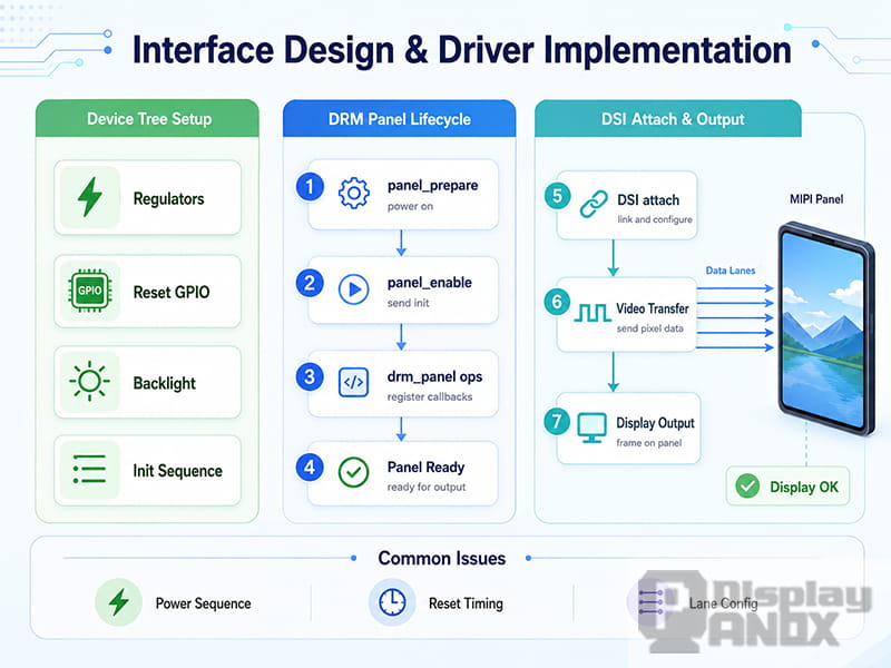
In the Linux DRM panel model, the panel driver usually separates the process into different stages. A common structure is:
-
prepare: enable regulators, apply reset, send initialization commands, exit sleep mode -
enable: turn the display on and enable the backlight -
disable: turn off backlight and display output -
unprepare: enter sleep mode and disable power rails
A simplified prepare function may include:
static int example_panel_prepare(struct drm_panel *panel)
{
    struct example_panel *ctx = to_example_panel(panel);

    regulator_enable(ctx->vdd);

    gpiod_set_value(ctx->reset, 1);
    msleep(20);
    gpiod_set_value(ctx->reset, 0);
    msleep(120);

    example_send_init_sequence(ctx);

    mipi_dsi_dcs_exit_sleep_mode(ctx->dsi);
    msleep(120);

    return 0;
}
This example is only a structure. Real projects should check the return value of each operation, especially regulator control, GPIO access, DSI command transmission, and backlight registration.
A common mistake is placing all operations in one function without considering suspend, resume, display blanking, or error recovery. This may work during the first boot but fail during screen-off, screen-on, or low-power resume.
6. Initialization Sequence: Do Not Copy Blindly
Panel initialization sequences are often provided by the panel vendor or controller IC supplier. They may include standard DCS commands and vendor-specific register writes. These commands configure gamma, voltage, timing, scan direction, color format, power settings, and other internal behavior.
However, a sequence from a reference platform should not be copied blindly. It may have been written for a different SoC, board, power design, or firmware environment.
Key points to verify include:
-
Whether each command is DCS write, generic write, short packet, or long packet
-
Whether the command format matches the current Linux DSI helper function
-
Whether the panel requires low-power command mode for initialization
-
Whether commands are allowed before or after video stream starts
-
Whether delays are required after reset, Sleep Out, and Display On
-
Whether the pixel format command matches the DRM format
-
Whether the panel is configured for video mode or command mode
-
Whether the panel expects burst, non-burst, sync pulse, or sync event video mode
-
Whether the initialization sequence includes brightness or display enable commands
Symptoms caused by incorrect initialization sequence may include:
-
Backlight on but no image
-
Image appears for a moment and disappears
-
Display works only after warm reboot
-
Colors are wrong
-
Image is shifted or cropped
-
Display flickers during boot
-
Panel fails after suspend and resume
For production designs, the initialization sequence should be reviewed together with the panel datasheet, vendor reference code, and actual hardware behavior.
7. Video Mode vs Command Mode
MIPI DSI displays generally use either video mode or command mode.
In video mode, the host continuously streams pixel data to the display. This mode is common for many LCD panels and embedded Linux systems. It is suitable for real-time display output where the panel expects a continuous video stream.
In command mode, the host updates the display through commands and memory writes. This mode is often used when the panel has internal GRAM or when partial refresh, lower power, or controlled updates are required.
Some panels support both modes, but the driver and DSI Host must be configured correctly. If a panel expects video mode but the host is configured for command mode, or if the panel initialization commands configure a different mode from the Linux display pipeline, the result may be a black screen or unstable image.
The selected mode affects:
-
DSI packet type
-
Clock behavior
-
Panel initialization sequence
-
Refresh behavior
-
Power consumption
-
Support for partial updates
-
Display controller configuration
-
DRM pipeline behavior
A reliable MIPI display solution starts by confirming the required mode from the panel datasheet or vendor support package.
8. Timing and Bandwidth: Check the Lane Rate Early
MIPI DSI timing is not only a display framework setting. It directly affects whether the DSI link can carry the required image data.
A simplified bandwidth estimate starts from the total pixel rate:
pixel_clock = htotal × vtotal × refresh_rate
raw_data_rate = pixel_clock × bits_per_pixel
lane_rate = raw_data_rate / number_of_lanes
Where:
-
htotalincludes active pixels, front porch, back porch, and sync width -
vtotalincludes active lines, front porch, back porch, and sync width -
bits_per_pixeldepends on RGB888, RGB666, RGB565, or other format -
number_of_lanesdepends on the panel and host hardware
In real designs, protocol overhead, PHY limitations, burst mode, blanking behavior, SoC margin, and vendor-specific requirements must also be considered. The simplified formula is still useful because it quickly reveals unreasonable settings.
For example, reducing a panel from four lanes to two lanes without adjusting the DSI clock may exceed the stable lane rate. Using RGB888 instead of RGB565 increases bandwidth demand. Increasing refresh rate from 60 Hz to 90 Hz also raises the lane rate significantly.
Timing-related problems may appear as:
-
No display output
-
Random flicker
-
Horizontal tearing
-
Image offset
-
Color noise
-
Edge jitter
-
Failure only at high brightness or high temperature
-
Failure only after cold boot
Display timing should always be checked together with lane count, pixel format, DSI clock, and panel mode flags.
9. Linux DRM/KMS: Make Sure the Pipeline Is Actually Active
On Linux systems, a MIPI display is usually part of the DRM/KMS graphics framework. The application layer may write to a framebuffer or submit a DRM buffer, but the image will not reach the panel unless the full display pipeline is active.
A typical DRM/KMS path may include:
-
Framebuffer or GEM buffer
-
Plane
-
CRTC
-
Encoder
-
Bridge
-
DSI Host
-
Panel
-
Backlight
The exact structure depends on the SoC and kernel driver. Some platforms use direct panel output. Others use one or more bridge chips before the final panel.
Useful debugging commands include:
dmesg | grep -Ei "drm|dsi|panel|backlight"

cat /sys/kernel/debug/dri/0/state

cat /sys/class/backlight/*/brightness
If debugfs is not mounted:
mount -t debugfs none /sys/kernel/debug
These checks help answer practical questions:
-
Is the panel driver probed?
-
Is the DSI Host attached?
-
Is the connector detected?
-
Is the selected mode correct?
-
Is the CRTC enabled?
-
Is the backlight registered?
-
Is the brightness value non-zero?
-
Are there DSI transmission errors in the kernel log?
If the DRM state shows an inactive connector or no complete pipeline, changing panel initialization commands may not solve the issue. The display chain must first be connected correctly at the DRM level.
10. Troubleshooting Common MIPI DSI Display Problems
10.1 Backlight Does Not Turn On
If the backlight is off, the display may look completely dead even when image data is present. This issue is more common on LCD modules.
Possible causes include:
-
Missing backlight node in the device tree
-
Wrong PWM channel
-
Wrong enable GPIO polarity
-
Brightness set to zero
-
Backlight power rail disabled
-
LED driver not initialized
-
Incorrect default brightness value
The first step is to check whether the backlight appears under /sys/class/backlight/. Then confirm the brightness value and measure the backlight power rail.
10.2 Backlight Is On but No Image Appears
This is one of the most common MIPI DSI troubleshooting scenarios. It usually means that the panel power or backlight is at least partially working, but the panel is not receiving or displaying valid image data.
Possible causes include:
-
Panel still in sleep mode
-
Display On command not sent
-
Wrong initialization command format
-
DSI attach failed
-
Incorrect video mode setting
-
Wrong lane count
-
Incorrect pixel format
-
DRM pipeline not active
-
DSI clock or timing mismatch
In this case, the control path and pixel path should be checked separately. The panel may not be initialized, or the Linux display pipeline may not be delivering frames.
10.3 Image Is Distorted or Colors Are Wrong
A distorted image is usually better than a black screen because it proves that some part of the display chain is working.
Possible causes include:
-
RGB888 configured as RGB666 or RGB565
-
Wrong color order
-
Incorrect porch timing
-
Lane rate too low
-
Wrong video mode flags
-
Incorrect horizontal or vertical active area
-
Mismatch between panel command settings and DRM mode
-
DSI packet mode mismatch
The pixel format should be checked in both the panel initialization sequence and the DRM mode configuration. Timing values should be compared with the panel datasheet, not only copied from a similar panel.
10.4 Display Works Sometimes but Fails Randomly
Intermittent MIPI DSI failures are often related to timing margin rather than one obvious wrong setting.
Possible causes include:
-
Power rail rise time too slow
-
Reset pulse too short
-
Delay after Sleep Out too short
-
DSI command sent before the panel is ready
-
Backlight enabled too early
-
Temperature-sensitive power behavior
-
Marginal lane rate
-
Weak FPC or connector contact
-
Suspend and resume sequence mismatch
For production hardware, intermittent startup failure is more dangerous than a stable failure because it may pass early tests and later appear in field use. The bring-up process should include repeated cold boot, warm boot, suspend/resume, brightness adjustment, temperature testing, and ESD recovery checks when required.
11. A Practical MIPI DSI Bring-Up Checklist
A structured checklist helps reduce debugging time and prevents circular troubleshooting.
| Stage | What to Check | Typical Tools |
|---|---|---|
| Schematic review | Power rails, reset polarity, backlight, lane count, connector pinout | Datasheet, schematic |
| Power validation | Voltage level, sequence, stability, current behavior | Multimeter, oscilloscope |
| Reset validation | Reset polarity, pulse width, delay after release | Oscilloscope |
| Backlight check | PWM, enable GPIO, brightness node, LED power | Sysfs, oscilloscope |
| Device tree | Regulator, GPIO, backlight, endpoint, DSI lanes, mode | DTS review, kernel log |
| Driver probe | Panel, DSI Host, bridge, backlight registration | dmesg |
| Panel prepare | Power, reset, initialization sequence, Sleep Out | Kernel log, trace points |
| Panel enable | Display On, backlight enable, brightness | Kernel log, sysfs |
| DRM/KMS state | Connector, CRTC, plane, mode, active pipeline | debugfs |
| Image path | Framebuffer, DRM buffer, application output | Test pattern, modetest |
| Stress testing | Cold boot, warm boot, suspend/resume, temperature | Repeated test cycles |
This checklist keeps the process grounded. Instead of changing random DSI parameters, each stage is verified with a measurable result.
12. How Panox Display Supports MIPI Display Integration
MIPI display integration can be complex because the panel is only one part of the complete system. The host processor, PCB layout, power design, driver IC, initialization sequence, software framework, and application requirements all affect the final result.
Panox Display supports embedded display projects with MIPI LCD, AMOLED, OLED, and Micro OLED modules for different product categories. Depending on the project, support may include:
-
Display module selection based on size, resolution, brightness, interface, and application
-
MIPI DSI panel specification review
-
Matching panel parameters with the host platform
-
Initial guidance on power, reset, and backlight requirements
-
Interface and connector information
-
Support for display timing and initialization requirements
-
Optional display solution discussion for Linux, Android, handheld, AR/VR, industrial, and custom devices
-
Controller board or adapter board solution evaluation when direct MIPI integration is not preferred
For some projects, a direct MIPI DSI connection is the best choice because it reduces board space and supports high-resolution display output. For other projects, an HDMI, USB Type-C, LVDS, RGB, or eDP-based display solution may reduce development risk and shorten integration time.
The right solution depends on the host platform, production volume, development schedule, mechanical design, software resources, and display performance target.
Conclusion
Lighting up a MIPI DSI display is not a single driver action. It is a complete engineering process that connects power design, reset timing, DSI Host setup, PHY configuration, panel initialization, DRM/KMS binding, backlight control, and application-level image output.
A reliable bring-up process starts from measurable hardware conditions, then moves through device tree configuration, panel driver sequencing, DSI timing, and display pipeline validation. Black screen, flicker, color errors, and intermittent startup failure should each be mapped to a specific part of the chain instead of treated as vague software problems.
For embedded display projects, this structured approach reduces debugging time and makes MIPI DSI display integration more predictable. With the right panel specification, correct initialization sequence, stable hardware design, and complete display pipeline, MIPI displays can deliver compact, high-resolution, and power-efficient visual solutions for modern electronic products.
Learn more: MIPI DSI PCB Layout Guidelines for Reliable Display Interfaces



