







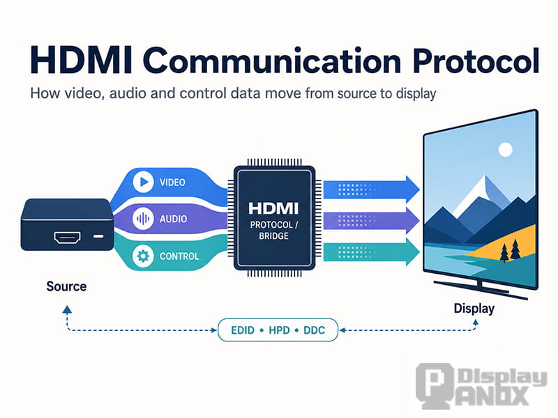
The HDMI communication protocol is commonly described as a way to send digital video and audio through one cable. That description is correct, but incomplete. An HDMI connection also needs to detect whether a display is present, identify the formats it supports, negotiate a compatible signal and, in some systems, exchange device-control or content-protection information.
For this reason, HDMI is better understood as a group of coordinated communication channels rather than one simple serial data protocol. The high-speed link carries video and audio, while supporting channels handle display identification, connection status and device control.
This distinction is particularly important in embedded display projects. A computer may have an HDMI output, but a bare TFT-LCD, AMOLED or OLED panel normally uses an internal panel interface such as MIPI DSI, LVDS, eDP or RGB. Connecting the two requires a controller board that receives the HDMI signal, processes it and generates the exact timing and electrical signals required by the panel.
What Is the HDMI Communication Protocol?
HDMI stands for High-Definition Multimedia Interface. It is a digital interface developed for transmitting uncompressed video, digital audio and related control data between a source and a receiving device.
An HDMI system normally contains three device roles. The source generates the signal, such as a computer, camera, game console or media player. The sink receives and displays or processes it, such as a monitor, projector or HDMI controller board. A repeater, such as an AV receiver or signal splitter, receives an HDMI signal and then retransmits it to another device.
The visible image is only one part of the communication. Before normal video transmission begins, the source and sink must establish that they are connected and determine which formats they can use together. HDMI performs this through separate signaling functions including Hot Plug Detect, the Display Data Channel and display identification data.
What Happens When an HDMI Device Is Connected?
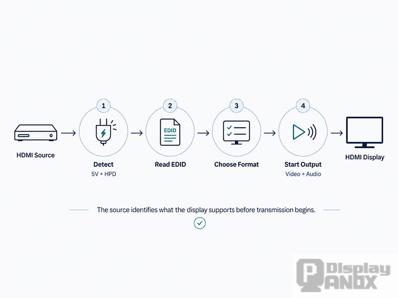
When an HDMI source is connected to a display, the source provides a 5 V signal through the interface. The receiving device uses Hot Plug Detect, usually shortened to HPD, to indicate that it is connected and ready for communication. HPD is not the video signal itself; it is a status signal that tells the source when it should begin reading the display information or restart the connection process. Texas Instruments describes the HDMI sink as holding HPD low until it is prepared to receive the signal, then asserting it so the source can continue.
The source then communicates with the display over the Display Data Channel, or DDC. DDC uses an I²C-based communication method and allows the source to read the display’s EDID, or Extended Display Identification Data. EDID tells the source which resolutions, refresh rates, timing formats and other display capabilities are available. VESA identifies EDID as the established mechanism that enables plug-and-play operation across display interfaces including HDMI.
After reading the EDID, the source selects a compatible output mode and begins high-speed transmission. If the source cannot read the EDID correctly, it may choose a fallback resolution, output an unsupported format or display no image at all. This is why a blank screen is not always caused by the LCD panel or HDMI cable; the failure may occur earlier in the connection sequence.
A simplified HDMI startup process is therefore:
-
The source supplies the HDMI 5 V signal.
-
The sink indicates readiness through HPD.
-
The source reads EDID through DDC.
-
The source selects a supported video and audio format.
-
High-speed video and audio transmission begins.
-
Optional functions such as HDCP, CEC or audio return may also become active.
How HDMI Carries Video and Audio
Traditional HDMI transmission uses TMDS, or Transition-Minimized Differential Signaling. A TMDS link includes three high-speed data channels and a separate clock channel. The encoding method reduces unnecessary signal transitions and helps maintain reliable transmission over the cable.
The three data channels do more than carry red, green and blue pixel values. Depending on the transmission period, they also carry audio packets, synchronization information and auxiliary data. HDMI audio is therefore embedded in the digital HDMI stream rather than being sent through a separate analog audio line.
For normal embedded display applications such as 1080p monitors, compact LCD systems and many industrial interfaces, TMDS-based HDMI receivers remain common. The receiver IC decodes the incoming HDMI stream and passes the resulting pixel data to a video processor, scaler or panel interface transmitter.
Newer high-bandwidth HDMI modes use FRL, or Fixed Rate Link. Unlike classic TMDS, FRL uses multiple high-speed data lanes operating at defined link rates and performs link training before normal transmission. The latest HDMI 2.2 Specification supports bandwidth up to 96 Gbps using next-generation FRL. HDMI 2.2 still requires TMDS support for backward compatibility with existing HDMI equipment.
The higher maximum bandwidth makes it possible to support formats such as uncompressed 4K at high refresh rates, higher color depths and larger resolutions. It does not mean that every HDMI controller board supports these modes. The actual capability depends on the HDMI receiver, processor, firmware, PCB design, output interface, panel resolution and cable.
The Main HDMI Communication Channels
An HDMI connector carries several functions that operate together:
| Channel or function | Purpose |
|---|---|
| TMDS or FRL | Carries high-speed digital video, audio and auxiliary data |
| DDC | Provides an I²C-based path for reading EDID and exchanging configuration data |
| EDID | Describes the display’s supported resolutions, timings and capabilities |
| HPD | Signals that the receiving device is connected and ready |
| CEC | Allows compatible HDMI devices to exchange control commands |
| HDCP | Protects licensed digital content when required |
| ARC or eARC | Returns audio from a display to an audio device |
| 5 V and ground | Supports connection detection and related HDMI interface functions |
CEC, or Consumer Electronics Control, is a low-speed single-wire bus. It allows HDMI-connected products to discover and control one another, making functions such as one-touch power control and shared remote operation possible. NXP describes CEC as a low-overhead bus intended to support communication and simplified system control between AV devices.
CEC does not carry the screen image. Similarly, DDC and HPD should not be confused with the main video lanes. A system may have valid TMDS electrical activity but still fail to produce an image if EDID, HPD or configuration handling is incorrect.
TMDS and FRL Are Not Panel Interfaces
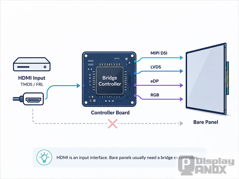
One of the most common misunderstandings in display development is assuming that an LCD with a digital interface can accept HDMI directly.
Most bare display panels do not contain a complete HDMI receiver. Instead, they expose an interface designed for communication between the panel and an internal host processor. Common examples include:
-
MIPI DSI for compact, high-resolution mobile and embedded displays
-
LVDS for industrial and medium-size LCD panels
-
eDP for laptop, monitor and higher-resolution display panels
-
RGB or parallel interfaces for embedded TFT-LCD modules
-
MCU or SPI interfaces for smaller and lower-data-rate modules
These interfaces have different electrical levels, packet structures, lane configurations, clocks and initialization requirements. An HDMI cable cannot convert between them by itself.
An HDMI controller board acts as the bridge. It receives the HDMI input, reads or provides the correct EDID, decodes the incoming video stream, scales or reformats the image when necessary and outputs the panel’s required interface. The board may also control backlight power, panel power sequencing, reset timing, touch communication and on-screen display functions.
Panox Display provides customized controller and driver boards with inputs such as HDMI, VGA, DVI, DisplayPort or Type-C, depending on the project. The output side can be configured for compatible LCD or OLED panel interfaces, with firmware and cable sets matched to the selected display. Panox Display also notes that controller boards have been developed for selected displays rather than every panel in the catalogue, so compatibility should be confirmed by panel model.
Why Controller Board Firmware Matters
Two LCD panels can have the same resolution and interface type but still require different controller-board configurations. Their horizontal and vertical timing, pixel clock, lane mapping, voltage sequence, backlight control and initialization commands may not be identical.
The controller firmware must normally contain the correct output timing and EDID information for the intended panel. For a MIPI display, it may also need a specific initialization command sequence. For an LVDS or eDP panel, it must match details such as lane count, bit mapping, link rate and color depth.
Using a board with the correct connector is therefore not enough. A physically compatible cable can still produce a black screen, unstable image, incorrect colors or repeated resets when the firmware and electrical settings do not match the panel.
A reliable controller-board request should include the full panel model number and datasheet. The native resolution, input source, desired refresh rate, touch requirement, power supply, backlight specification and expected operating environment should also be provided.
HDMI Bandwidth and Display Resolution
Resolution alone does not determine how much HDMI bandwidth a system needs. Refresh rate, color depth, chroma format and blanking intervals also affect the required data rate.
For example, a 4K signal at 30 Hz requires less bandwidth than 4K at 60 Hz, while 10-bit or 12-bit color requires more data than 8-bit color. Full 4:4:4 chroma also carries more color information than 4:2:2 or 4:2:0.
This matters when selecting a controller board. A board advertised as supporting “4K” may only support that resolution at a particular refresh rate or chroma setting. The panel output interface must also provide enough bandwidth. An HDMI receiver capable of accepting a high-resolution signal is not useful if the scaler or panel interface cannot deliver the panel’s required native timing.
Specification version labels should not be treated as a complete description of capability. HDMI Licensing Administrator has stated that HDMI version numbers are not feature sets and that manufacturers should identify the supported features alongside the version claim. In practice, resolution, refresh rate, bandwidth, HDR, color depth, HDCP and audio support should be verified individually.
Common HDMI Display Problems
No Signal or Black Screen
A black screen can occur when HPD is not asserted, DDC communication fails, EDID is missing or corrupted, or the source selects a mode that the controller cannot process. It can also result from incorrect panel firmware, power sequencing or MIPI initialization.
Testing should begin by confirming that the source detects a connected display and reports the expected EDID. After that, verify the HDMI input resolution and the controller board’s panel configuration.
Image Appears but the Resolution Is Wrong
This usually indicates that the source is using a fallback mode or that the EDID does not advertise the required native resolution. A scaler may also be converting the input to another output timing.
The controller firmware and EDID should be matched to the actual panel resolution rather than copied from a different display.
Intermittent Image, Sparkles or Dropouts
These symptoms often point to signal-integrity problems. Cable quality, cable length, connector condition, PCB trace impedance, grounding and the HDMI receiver’s equalization capability can all affect the link.
Higher data rates provide less tolerance for poor routing and loss. A cable that works reliably at 1080p may fail when the source is changed to a higher resolution, refresh rate or color depth.
Image Works on One Source but Not Another
Different computers, cameras and media devices may interpret EDID or connection timing differently. One source may fall back to a safe resolution, while another may stop transmitting when the handshake is incomplete.
Testing with several sources is useful, but the correct solution is to repair the EDID, HPD or firmware behavior rather than depend on one device’s fallback logic.
Protected Video Does Not Play
Normal desktop content may display correctly while protected streaming or commercial media remains black. In that case, the issue may involve HDCP support, authentication or version compatibility rather than basic HDMI video transmission.
The complete signal chain—including source, converter, controller and sink—must support the required content-protection method.
How to Select an HDMI Controller Board
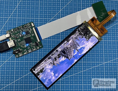
6.5 inch flexible OLED with HDMI Board
For a new LCD or OLED display project, begin with the panel rather than choosing a generic controller board first. The controller must be selected around the panel’s electrical and timing requirements.
Confirm the following information before ordering or developing the board:
-
Exact panel model and datasheet
-
Native resolution and refresh rate
-
Panel interface and lane configuration
-
Required HDMI input formats
-
Color depth and chroma requirements
-
Touchscreen interface
-
Backlight voltage and current
-
Power supply and power sequencing
-
Mechanical space and connector direction
-
Operating temperature and application environment
For high-resolution MIPI, LVDS or eDP panels, it is also important to verify whether the controller performs scaling or only accepts the panel’s native timing. A board described as HDMI-to-MIPI or HDMI-to-eDP may not support every panel using that interface.
Panox Display can match selected TFT-LCD, AMOLED and OLED panels with suitable HDMI or Type-C controller solutions. Where an existing controller is not available, a customized board may require evaluation of the panel timing, receiver IC, bridge device, firmware, cable set and mechanical layout.
Conclusion
The HDMI communication protocol is a coordinated system for transmitting digital video, audio, display capabilities and control information. TMDS or FRL carries the high-speed media data, while HPD, DDC and EDID manage connection detection and format selection. Optional functions such as CEC, HDCP and audio return add device control, content protection and audio routing.
In a display integration project, HDMI is normally the input interface of a controller board rather than the native interface of the LCD or OLED panel. Reliable operation depends on more than the connector: EDID, timing, bandwidth, firmware, signal integrity, panel initialization and power sequencing must all be matched correctly.
For this reason, the safest way to develop an HDMI display system is to evaluate the source, controller board and panel as one complete signal path rather than three interchangeable components.
Learn more: HDMI Display Interface Explained: Signal Principles, Bandwidth, Versions, and Display Solution Selection



