







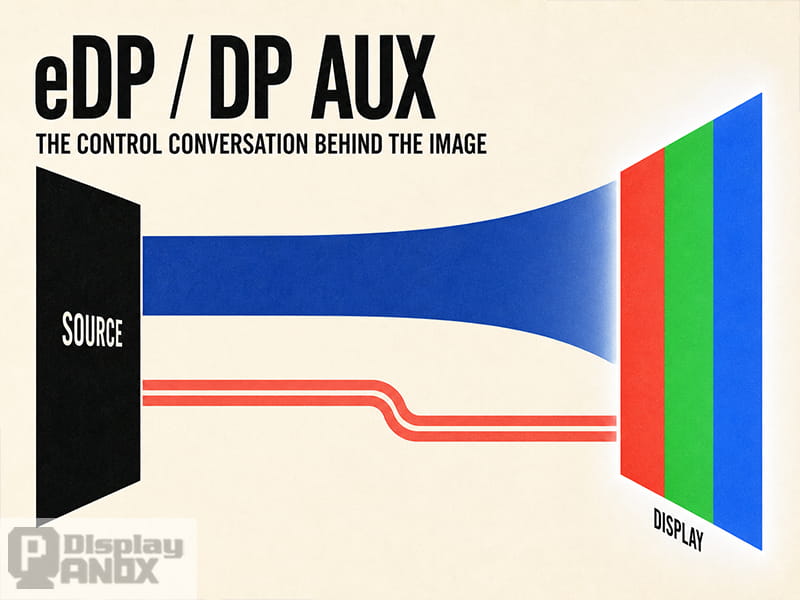
A DisplayPort Main Link can be routed correctly and a display can still remain black. In many bring-up cases, the missing piece is not the high-speed video lane but the DisplayPort AUX channel.
The Main Link carries video and audio data in one direction, from the Source to the Sink. The AUX channel, formed by AUX_P and AUX_N, is a bidirectional, half-duplex differential control path. Both endpoints share the same pair and take turns transmitting and receiving. A problem in either direction can interrupt EDID access, DPCD communication, link training, HDCP authentication or eDP panel configuration.
This is why the AUX channel deserves attention even though its data rate is much lower than that of the Main Link. Incorrect signal amplitude, unsuitable bias resistors, missing AC coupling, wrong bridge settings or poor PCB routing can prevent the video link from starting at all.
For Panox Display projects, AUX integrity is treated as a core part of Embedded DisplayPort (eDP) interface design, especially when integrating high-resolution LCD or OLED panels, bridge ICs and custom controller boards.
What Is the eDP or DisplayPort AUX Channel?
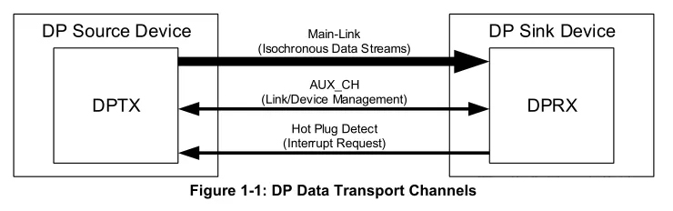
A DP or eDP connection contains three paths with different responsibilities.
| Signal path | Direction | Main purpose |
|---|---|---|
| Main Link | Source to Sink | Carries video, audio and Main Link training patterns |
| AUX Channel | Bidirectional, half-duplex | Carries management, configuration and status data |
| HPD | Primarily Sink to Source | Reports display presence, readiness and interrupt events |
The AUX channel does not carry the visible video stream. Its job is to establish, configure and maintain the connection that allows the Main Link to operate.
AUX transactions can be divided into two main types. Native AUX transactions read and write DPCD registers, while I²C-over-AUX transactions transport I²C commands such as EDID reads. The conventional AUX mode discussed in this guide uses Manchester-II encoding and operates at approximately 1 Mbps.
This architecture is described in both Intel’s DisplayPort AUX design guidance and TI’s DP/eDP link-training application note.
How HPD and AUX Communication Start a DisplayPort Connection
In a typical external DisplayPort connection, the Sink is a monitor, projector or bridge device, while the Source is a GPU, computer, docking station or display controller.
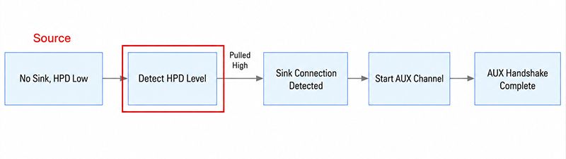
When the Sink is connected, powered and ready for communication, it asserts the HPD signal. The Source detects HPD high and begins communicating with the Sink through the AUX channel. It reads DPCD capability registers, retrieves EDID data, selects a supported link rate and lane count, and then begins DisplayPort link training.
A simplified startup sequence is:
- The Sink becomes available and asserts HPD.
- The Source reads the Sink’s DPCD capabilities through native AUX transactions.
- The Source reads EDID or DisplayID information through I²C-over-AUX.
- A suitable lane count and link rate are selected.
- Main Link training patterns are transmitted while AUX carries status and adjustment requests.
- Video transmission begins after link training succeeds.
AUX carries the instructions and feedback used during link training, but the training patterns themselves travel over the Main Link. This distinction matters during fault diagnosis: a valid AUX exchange does not automatically prove that the Main Link has sufficient signal quality.
TI provides a detailed description of this sequence in its DisplayPort/eDP link-training guide.
HPD Behavior in eDP Systems
External DisplayPort is designed for hot-plug operation. An eDP panel is normally a fixed internal component and is not expected to be connected or removed while the product is operating.
For this reason, HPD is optional in some eDP implementations. A system may use a dedicated HPD signal, hold it in a defined state or replace the plug-detection event with a controlled panel power-up delay. The correct implementation depends on the SoC, bridge IC, TCON and panel specification.
The panel must still be powered and ready before AUX transactions begin. Attempting to read DPCD or EDID while an eDP panel is unpowered commonly results in AUX timeouts.
DisplayPort AUX Channel Electrical Specifications
Two measurements are especially useful when evaluating a DP AUX signal: timing and differential amplitude.
The conventional AUX channel operates at approximately 1 Mbps. Its Manchester transaction unit interval is nominally 0.5 µs, with the applicable specification allowing a range around that nominal value. A waveform that is clearly outside this timing window may not be decoded reliably by the receiving PHY.
Differential amplitude must be evaluated against the correct interface type and test point. DP and eDP do not use identical minimum values.
The following figures are summarized from TI’s March 2026 application note, which references DP 1.4a and eDP 1.4b electrical requirements. Later specifications, including eDP 1.5a, and individual component data sheets should be checked for final compliance limits.
| Parameter | Minimum | Nominal | Maximum |
|---|---|---|---|
| Manchester transaction unit interval | 0.4 µs | 0.5 µs | 0.6 µs |
| DP AUX transmitter differential amplitude | 0.29 Vp-p | 0.40 Vp-p | 1.38 Vp-p |
| DP AUX received amplitude at TP2 or TP3 | 0.27 Vp-p | — | 1.36 Vp-p |
| eDP AUX transmitter amplitude at TP1 | 0.18 Vp-p | 0.20 Vp-p | 1.38 Vp-p |
| eDP AUX amplitude at TP3 | 0.14 Vp-p | — | 1.36 Vp-p |
| DP AUX DC common-mode voltage | 0 V | — | 2.0 V |
| eDP AUX DC common-mode voltage | 0 V | — | 1.2 V |
| AUX turnaround common-mode shift | 0 V | — | 0.3 V |
| External AUX coupling capacitor | 75 nF | 100 nF commonly used | 200 nF |
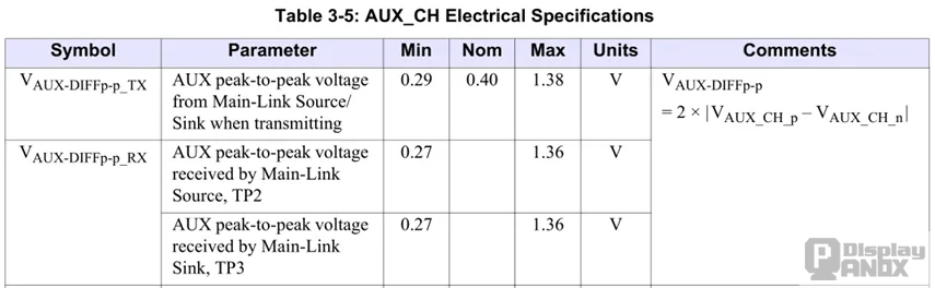
For a DP transmitter eye mask, the minimum differential boundary of +145 mV to −145 mV corresponds to 0.29 Vp-p. At a DP receiving point, +135 mV to −135 mV corresponds to the 0.27 Vp-p receiver minimum.
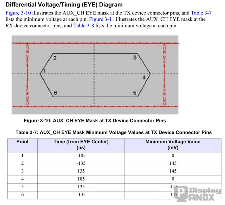
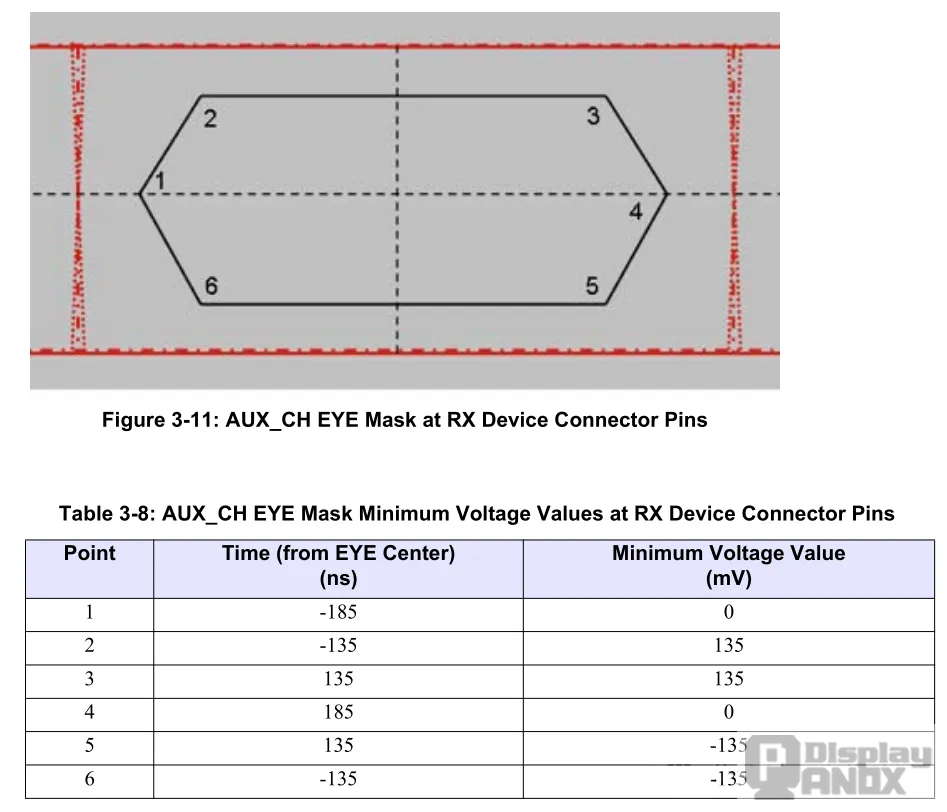
These values are differential peak-to-peak measurements. A single-ended measurement on AUX_P or AUX_N should not be compared directly with the differential specification.
TP2 and TP3 Measurement Points
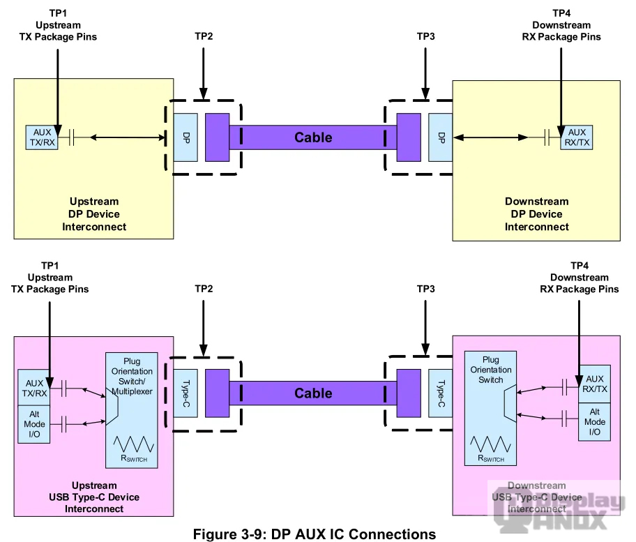
Because AUX is bidirectional, the measurement direction must be recorded with the waveform.
TP2 is located on the Source side of the link. When the Sink sends an AUX response back to the Source, that response can be evaluated at TP2. TP3 is located on the Sink side. When the Source sends a request to the Sink, the received signal can be checked at TP3.
Testing only the Source-to-Sink direction can miss a weak bridge or panel transmitter. The same applies in reverse: a clean Sink response does not prove that the Source request reaches the Sink with sufficient margin.
Probe loading, termination, bandwidth, differential calculation and the physical test location all affect the displayed waveform. These conditions should be documented before comparing a measured value with the specification.
DP and eDP AUX Pull-Up and Pull-Down Differences
A conventional external DP interface uses a defined DC bias network around the AC-coupling capacitors.
On the Source side, AUX_P is weakly pulled down and AUX_N is weakly pulled up. On the Sink side, the polarities are reversed with higher resistor values.
| Endpoint | AUX_P bias | AUX_N bias |
|---|---|---|
| DP Source | 100 kΩ pull-down to ground | 100 kΩ pull-up to DP_PWR |
| DP Sink | 1 MΩ pull-up | 1 MΩ pull-down to ground |
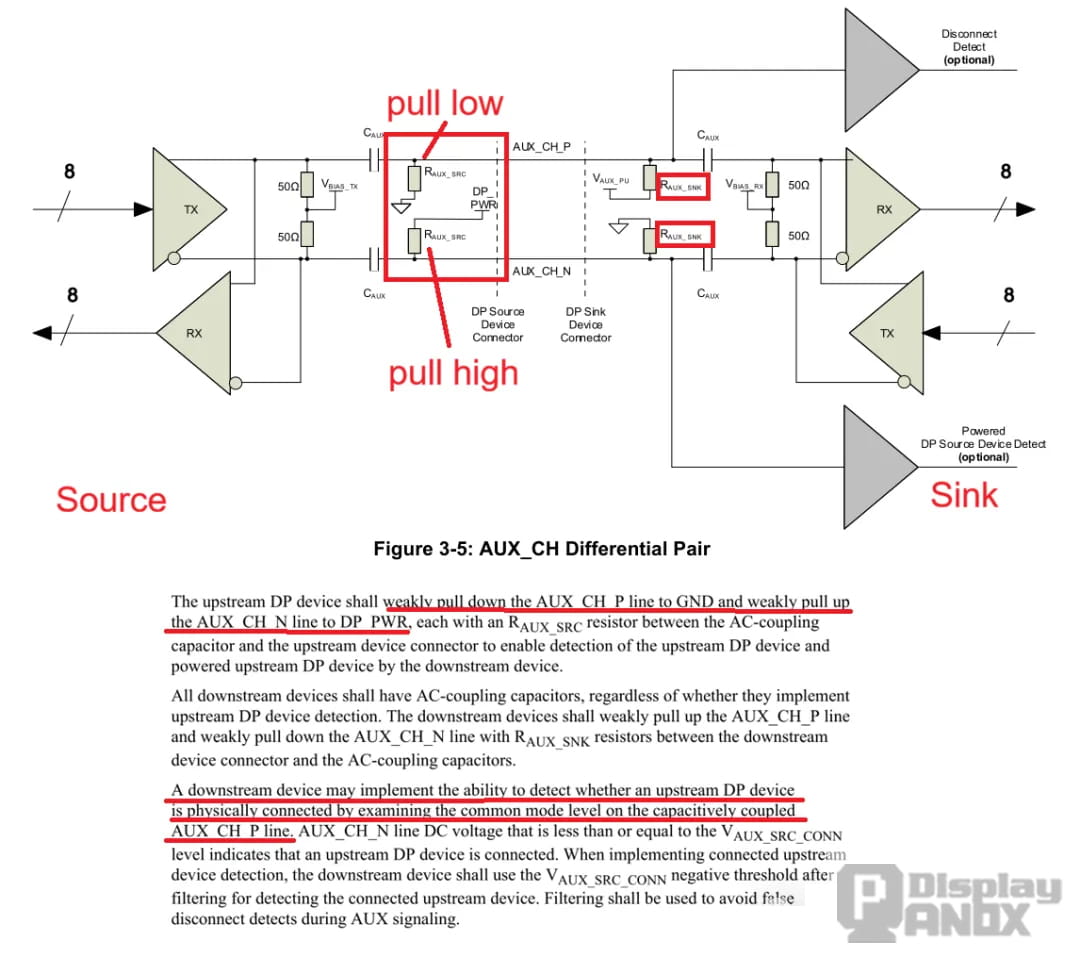
These resistors are placed between the DP connector and the AC-coupling capacitors. Some PHYs, redrivers and bridge ICs integrate part or all of this network, so the device data sheet must be checked before adding external components.
The arrangement allows a Sink that supports Source Detection to evaluate the DC state of the AUX lines:
- AUX_P at a low level indicates that a Source is connected.
- AUX_N at a high level indicates that the connected Source is powered.
This detection mechanism does not replace HPD. The two signals operate in opposite directions: HPD allows the Source to detect a ready Sink, while the AUX bias network allows the Sink to detect a connected or powered Source.
Intel’s DisplayPort design guide documents the 100 kΩ Source network, the 1 MΩ Sink network and their role in upstream-device detection.
Why Source Detection Is Useful in External DP
Source Detection can improve three common external DisplayPort conditions.
First, a Sink that detects no Source can remain in a lower-power standby state instead of asserting HPD or attempting unnecessary communication.
Second, it helps with the “cable first, Source power later” sequence. If a monitor is connected before the computer starts, the Sink can detect the cable and wait until AUX_N indicates that the Source is powered. HPD can then be asserted at the appropriate time, reducing the possibility of a missed startup handshake.
Third, the Sink can distinguish among an open connector, a connected but unpowered Source and a normally powered connection. HPD alone does not provide the same three-state information.
Why the eDP Circuit Is Often Different
An eDP panel is generally installed as a fixed internal component. Cable attachment detection is therefore less important than it is for an external DP connector.
Many eDP reference designs omit the external Source-Detection resistors or reserve their footprints as DNP components. TI’s current DP/eDP application note shows both valid eDP stuffing approaches: one with the 100 kΩ and 1 MΩ networks populated, and another with those resistors omitted.
The final decision depends on the panel and bridge implementation. Some eDP Sinks still expect Source-Detection biasing, while other panels operate without it. Reserving resistor footprints during an early prototype can provide useful flexibility, but production population should follow the panel, SoC or bridge reference design.
What Data Does the DisplayPort AUX Channel Carry?
EDID and DisplayID Information
The Source uses I²C-over-AUX to read EDID data from the display. EDID identifies supported resolutions, timing modes, refresh rates and other display characteristics. Depending on the EDID extension blocks, it may also describe color information and audio capabilities.
This function is similar to the DDC/I²C path used by HDMI. The difference is that DisplayPort carries the I²C transaction over the AUX differential pair rather than using a separate exposed SDA/SCL pair.
A failed EDID read can cause missing display detection, an incorrect default resolution or repeated initialization attempts.
DPCD Register Access
DPCD stands for DisplayPort Configuration Data. It is the native register space through which the Source reads capabilities and the Sink reports status.
DPCD contains information such as maximum link rate, supported lane count, training capabilities, link status and various feature controls. In eDP systems, supported DPCD registers may also control panel power states, backlight behavior, self-test functions and other panel-specific features.
Not every eDP panel supports every AUX-based control. Backlight enable, PWM control and brightness adjustment may still use dedicated pins, depending on the panel design.
DisplayPort Link Training
Before video can travel over the Main Link, the Source and Sink must establish a stable physical connection.
The Source reads the Sink’s capabilities and configures a compatible link rate and lane count. Common DP 1.x link rates include RBR, HBR, HBR2 and HBR3, while the number of active lanes is typically one, two or four.
During training, the Source transmits training patterns over the Main Link. The Sink checks clock recovery, channel equalization, symbol lock and lane alignment. It then returns status and adjustment requests through DPCD registers over AUX.
If AUX communication fails, the Source cannot obtain reliable training feedback. The result may be repeated training attempts, fallback to a lower rate or complete failure to establish the video link.
HDCP Authentication
HDCP authentication, key exchange and status communication also use the AUX channel. The protected audio/video content remains on the Main Link.
An AUX problem can therefore appear as an HDCP or protected-content failure even when unprotected desktop output is available.
eDP Panel and Backlight Control
VESA added panel and backlight control capabilities to eDP through the bidirectional AUX channel. Depending on the panel, these functions may include brightness control, backlight modulation, dynamic backlight modes, self-test functions, color-engine control and panel power management. These capabilities are described in VESA’s eDP control overview.
AUX is also involved in advanced eDP features such as Panel Self Refresh. A separate Panox Display guide explains how Panel Self Refresh and Dynamic Refresh Rate operate in DP/eDP displays.
Schematic Design Guidelines for DP and eDP AUX
Use the Correct AC-Coupling Network
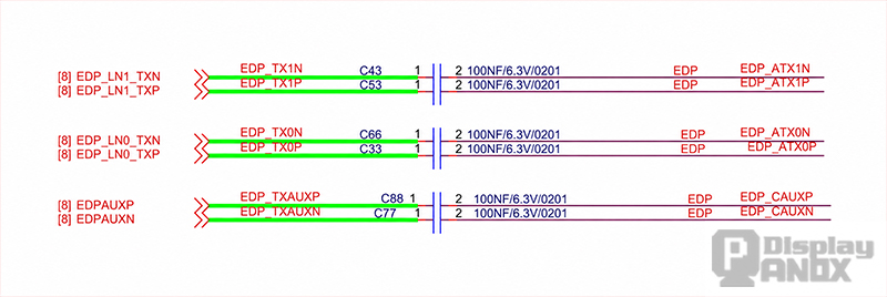
The AUX pair is AC coupled because the Source and Sink can operate with different common-mode bias voltages. For a conventional external DP implementation, both endpoints contain the required coupling arrangement.
The specified external capacitor range is generally 75–200 nF, with 100 nF being a common value. Both capacitors should use the same value, package and placement geometry.
Some bridge ICs and PHYs already contain internal coupling capacitors. Adding another set without checking the internal architecture can alter the intended response. Conversely, omitting required external capacitors can prevent communication completely.
In an eDP design, one side of the connection may permit a 0 Ω stuffing option instead of an additional Sink-side capacitor. This is implementation-dependent and should never be decided from a generic circuit alone.
Confirm the AUX Bias Resistors
A standard external DP port normally needs the Source and Sink bias network described earlier. The component placement must be on the connector side of the AC-coupling capacitors for Source Detection to work correctly.
For eDP, the resistors can be reserved but left unpopulated when the selected panel and bridge support that configuration.
Wrong polarity is a serious fault. AUX_P should not be given the AUX_N bias network, and the 100 kΩ Source values should not be substituted for the 1 MΩ Sink values without a device-specific reason.
Follow the Bridge IC Reference Design
A DP-to-HDMI bridge acts as a DP Sink on its DisplayPort side. Its AUX transmitter, receiver, internal termination, bias network and clock configuration may differ from those of an SoC-integrated DP PHY.
Designs based on bridge devices such as LT8711 or GSV2201 should follow the latest bridge schematic and initialization documentation. Some bridge reference designs route AUX directly through the specified coupling capacitors, while others include internal components that must not be duplicated.
The bridge’s AUX clock divider and drive-strength registers also require verification during software bring-up. A correct schematic cannot compensate for an AUX transmitter configured to the wrong timing or amplitude.
Add Suitable ESD Protection
An external DP connector should include ESD protection for AUX_P and AUX_N. The protection device should have low and well-matched capacitance, low leakage and suitable clamping performance.
Placement should be close to the connector, with a short ground-return path. Long branches between the connector, ESD device and main AUX route create stubs and unnecessary impedance discontinuities.
Reserve Practical Debug Access
AUX test access can save significant time during the first prototype. Test pads should be placed symmetrically and in line with the pair rather than as long side branches. Stubbed test points can disturb the waveform and create misleading measurements.
DisplayPort AUX Channel PCB Layout Guidelines
AUX_P and AUX_N should be routed as a controlled differential pair. TI’s eDP bridge implementation guide specifies 100 Ω differential impedance, with the final tolerance determined by the PHY, connector and PCB stack-up.
The two traces should remain together with consistent width and spacing. AUX length matching is generally less demanding than Main Link lane matching because the data rate is much lower, but this does not justify visibly asymmetric routing. Component pads, vias and layer changes should load both sides of the pair equally.
A continuous ground reference is essential. The pair should not cross ground-plane splits, voids or changes in return-path geometry. If a layer transition is unavoidable, nearby ground stitching vias help maintain the return path.
Ground copper or guard traces may be placed on both sides of the AUX pair when the impedance model accounts for them. A solid reference plane is more important than adding side guards, and poorly spaced ground traces can change the intended differential impedance.
The pair should also be separated from switching power nodes, inductors, high-current paths, fast clocks and other strong noise sources. Vias should be minimized, and via stubs should be avoided. ESD devices, coupling capacitors and connectors should preserve pair symmetry.
TI’s SN65DSI86/SN65DSI96 implementation guide provides a practical reference for AC coupling, optional eDP bias resistors and 100 Ω AUX routing.
Troubleshooting DisplayPort AUX and Link-Training Failures
AUX problems often resemble Main Link failures because both can end with the same symptom: no image.
A useful debug sequence begins before Main Link equalization is changed:
- Confirm that the panel, bridge or monitor is powered in the correct sequence.
- Check HPD behavior and determine whether HPD is required for the selected eDP implementation.
- Verify that DPCD and EDID transactions receive valid replies.
- Measure AUX timing and amplitude in both communication directions.
- Confirm AC-coupling, bias-resistor and ESD component population.
- Inspect DPCD link-status registers and training logs.
- Evaluate the Main Link only after AUX configuration and status communication are stable.
Case 1: The DP AUX Signal Measures About 200 mV
For an external DP interface, a confirmed 200 mV differential peak-to-peak waveform is below the 0.29 V transmitter minimum and the 0.27 V receiver-side minimum quoted above.
The reduced margin can produce intermittent AUX decoding. EDID or DPCD reads may fail, link training may stop before completion, and the product may show a probabilistic black screen during startup.
Possible causes include an incorrect AUX drive-strength setting, unsuitable coupling capacitors, excessive ESD-device loading, incorrect bias resistors, connector loss, probe loading or asymmetric routing.
The interface type and test point must be identified before making this diagnosis. An eDP transmitter can use a nominal amplitude near 200 mV at TP1, so the external DP minimum cannot be applied blindly to an eDP waveform.
Case 2: A Bridge IC Transmits AUX at About 0.8 Mbps
The conventional AUX channel is designed around a nominal 1 Mbps transfer rate. If a bridge IC is producing a decoded rate near 0.8 Mbps and its Manchester timing falls outside the permitted unit-interval range, the Source may misread the response or wait until the transaction times out.
The bridge clock source, divider and AUX configuration should be corrected to the vendor’s nominal 1 Mbps setting. The waveform should then be checked in both directions.
A universal failure threshold should not be assigned to exactly 0.8 Mbps because receiver tolerance, jitter, waveform quality and measurement method vary. It is also important to distinguish the decoded data rate from the visible transition rate of Manchester-II encoding.
When the timing is genuinely outside the required range, likely symptoms include invalid AUX replies, failed DPCD reads, unsuccessful DisplayPort link training and a black screen.
Final Design Takeaways
The DisplayPort AUX channel runs at a relatively low data rate, but it decides whether the high-speed video path can be established. A reliable implementation depends on correct bidirectional timing, adequate differential amplitude, the proper DP or eDP bias network, suitable AC coupling, low-capacitance protection and controlled differential routing.
External DisplayPort and internal eDP should not be treated as identical circuits. External DP uses HPD and Source Detection to manage hot-plug behavior, while eDP normally operates as a fixed internal connection with product-specific power sequencing and optional bias components.
When a display has unstable detection, repeated link training or an intermittent black screen, AUX should be checked before extensive changes are made to the Main Link. A clean EDID read, reliable DPCD access and valid AUX waveforms in both directions provide the foundation for a stable DP or eDP display system.
Panox Display supports eDP LCD and OLED panel selection, connector matching, custom controller boards and eDP-to-HDMI or Type-C integration. Reviewing the panel, bridge, power sequence and AUX implementation as one system helps reduce prototype rework and shortens the path to a stable display solution.



