







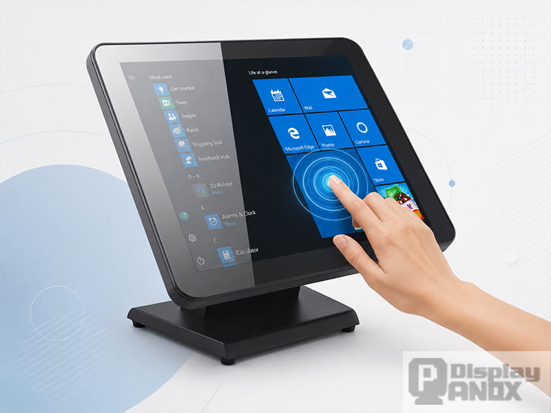
Capacitive touch screens have become a common interface for smartphones, tablets, smart appliances, medical equipment, industrial control panels, automotive displays, and self-service terminals. They respond to a light finger touch, support familiar gestures, and can be integrated with LCD, OLED, and AMOLED display modules.
The technology may appear simple from the outside, but reliable touch performance depends on the complete system: the sensor pattern, cover lens, bonding material, touch controller, display noise, mechanical structure, firmware, and operating environment.
This article explains how a capacitive touch screen works, the difference between surface capacitive and projected capacitive technology, the roles of self-capacitance and mutual capacitance, and the factors that matter when selecting a capacitive touch display.
What Is a Capacitive Touch Screen?
A capacitive touch screen is a touch-sensitive interface that detects changes in electrical capacitance when a conductive object, usually a human finger, approaches or touches its surface.
A transparent conductive sensor is positioned over or integrated with the display. The touch controller continuously measures the electrical condition of the sensor. When a finger interacts with the electric field, the measured capacitance changes. The controller processes that change, calculates the touch coordinates, and reports the input to the host system.
Unlike a resistive touch screen, a capacitive touch screen does not need two flexible conductive layers to be pressed together. A light contact is normally enough to register an input.
Capacitive Touch Panel vs. Capacitive Touch Display
The terms are closely related but do not always describe the same component.
A capacitive touch panel, also called a CTP, is the touch-sensing component. It may include the sensor, cover lens, touch controller, flexible cable, and bonding layers.
A capacitive touch display combines the touch panel with a visual display such as a TFT LCD, OLED, or AMOLED module.
The display produces the image. The capacitive touch panel detects the input. These two systems must work together, but their signals, interfaces, and controllers are usually handled separately.
How Does a Capacitive Touch Screen Work?
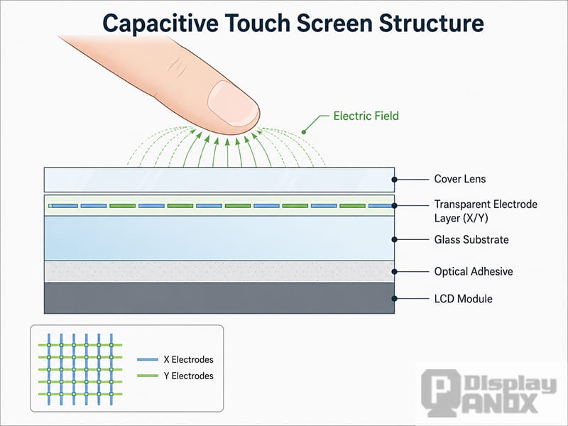
Capacitance describes the ability of an electrical structure to store charge. In a capacitive touch system, conductive electrodes create an electric field near the surface of the panel.
The basic operating process can be divided into five stages.
1. The Touch Controller Scans the Sensor
The touch controller sends and measures electrical signals across the transparent electrode pattern. Depending on the sensing method, it may measure the capacitance of individual electrodes or the coupling between transmit and receive electrodes.
2. A Finger Enters the Electric Field
The human body is electrically conductive and is coupled to earth ground. When a finger touches or approaches the panel, it changes the electric field around the nearby electrodes.
3. The Local Capacitance Changes
In a self-capacitive system, a finger generally increases the measured capacitance of an electrode.
In a mutual-capacitive system, a finger disturbs the field between a transmit electrode and a receive electrode, reducing the coupling measured at that sensor node.
4. The Controller Calculates the Coordinates
The controller compares the new sensor values with a continuously updated baseline. Signal-processing algorithms filter noise, identify valid touches, reject unintended inputs, and calculate the X and Y coordinates.
5. The Touch Data Is Sent to the Host
The coordinates are transmitted to the main processor through an interface such as I²C, SPI, USB, or another interface supported by the controller and host platform. The operating system or application then converts the coordinates into actions such as tapping, scrolling, dragging, pinching, or zooming.
Main Components of a Capacitive Touch Screen
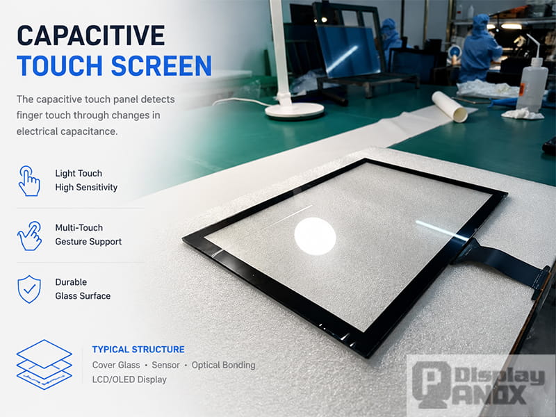
A complete capacitive touch solution contains more than a transparent sensor. Each layer affects optical quality, sensitivity, durability, and environmental performance.
Cover Lens
The cover lens is the outer surface touched during operation. It is commonly made from strengthened glass, although plastic materials may be used when weight, impact behavior, shape, or cost has greater importance.
The cover lens can be customized with:
-
Printed borders and logos
-
Transparent display windows
-
Anti-glare treatment
-
Anti-fingerprint coating
-
Anti-reflective treatment
-
Custom holes and cutouts
-
Rounded or irregular outlines
-
Increased thickness for impact protection
A thicker cover lens can improve mechanical protection, but it also increases the distance between the finger and the sensor. Electrode geometry, controller sensitivity, signal-to-noise ratio, and firmware tuning must therefore be considered together.
Transparent Touch Sensor
The sensor contains patterned conductive electrodes. Indium tin oxide, commonly known as ITO, has traditionally been used because it combines electrical conductivity with optical transparency. Other conductive materials and sensor structures may be selected for large, curved, flexible, or specialized touch panels.
In a projected capacitive panel, the electrodes usually form an X-Y matrix. Each intersection or sensing region can contribute to the calculation of touch position.
Optical Adhesive or Air Gap
The touch panel can be attached to the display with perimeter adhesive, leaving an air gap, or bonded across the full visible area with an optical adhesive.
Optical bonding can reduce internal reflections, improve perceived contrast, and provide a more solid mechanical assembly. However, the adhesive, display polarizer, sensor, cover glass, and bonding process must be compatible.
Touch Controller IC
The touch controller drives the sensor electrodes, measures very small capacitance changes, filters interference, calculates touch coordinates, and communicates with the host processor.
Controller capability strongly affects:
-
Number of simultaneous touch points
-
Touch latency
-
Gesture response
-
Glove operation
-
Wet-finger tracking
-
Water rejection
-
Palm or grip rejection
-
Stylus support
-
Thick-cover operation
-
Electromagnetic noise immunity
-
Power consumption
Modern controllers may combine self-capacitive and mutual-capacitive scanning to improve performance under difficult conditions.
FPC and Host Interface
A flexible printed circuit connects the touch sensor and controller to the main board. Its shape, pin definition, connector position, bending area, and overall length must match the mechanical design.
Common controller-to-host communication options include I²C and SPI. USB may also be used in display modules intended for computers, industrial PCs, or plug-and-play systems. Interface selection depends on the controller, operating system, driver support, cable length, and host architecture.
Types of Capacitive Touch Screens
Capacitive touch technologies are often described with overlapping terms. A clearer classification separates the physical panel type from the electrical sensing method.
The two main panel categories are:
-
Surface capacitive touch screens
-
Projected capacitive touch screens
Self-capacitance and mutual capacitance are sensing methods commonly used within capacitive systems, particularly projected capacitive designs.
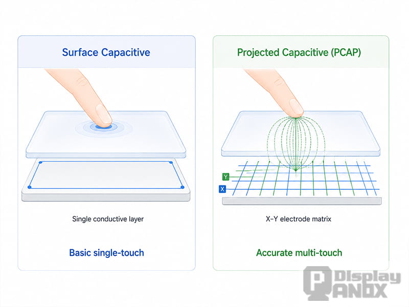
Surface Capacitive Touch Screen
A surface capacitive touch screen uses a uniform transparent conductive coating on one side of a glass substrate. Electrical signals are applied around the panel. When a finger touches the surface, a small current is drawn from the corners or edges, and the controller estimates the touch location.
Surface capacitive technology offers a durable glass surface and can be suitable for basic single-touch interfaces. However, it is generally less suitable for precise multi-touch gestures and complex modern user interfaces.
Typical applications have included:
-
Basic kiosks
-
ATMs
-
Ticketing terminals
-
Public information displays
-
Legacy industrial interfaces
Projected Capacitive Touch Screen
A projected capacitive touch screen, commonly called PCAP, P-CAP, or PCT, uses a patterned matrix of transparent electrodes. The electric field projects through an insulating cover surface, allowing the sensor to detect a finger without direct contact with the conductive layer.
PCAP is widely selected for modern touch displays because it can provide:
-
Accurate coordinate detection
-
Light-touch activation
-
Multi-touch operation
-
Pinch, zoom, swipe, and rotation gestures
-
A durable cover-glass surface
-
High electrode density
-
Narrow-border product designs
-
Support for advanced touch controllers
-
Integration with LCD and OLED displays
Projected capacitive technology may use self-capacitive sensing, mutual-capacitive sensing, or a combination of both.
Self-Capacitance vs. Mutual Capacitance
Self-capacitance and mutual capacitance describe how the electrodes are measured. They are not simply two unrelated touch-panel products.
Self-Capacitive Sensing
In a self-capacitive system, the controller measures the capacitance of an individual electrode relative to ground. A nearby finger adds capacitance to that electrode.
Self-capacitive sensing can provide high sensitivity and may be useful for:
-
Single-touch detection
-
Touch buttons
-
Sliders
-
Proximity sensing
-
Hover functions
-
Operation through thicker overlays
However, an electrode matrix based only on self-capacitance can have difficulty distinguishing certain simultaneous touches. When multiple rows and columns are activated, the system may produce ambiguous intersections known as ghost points.
Mutual-Capacitive Sensing
A mutual-capacitive sensor uses separate transmit and receive electrodes. Each crossing forms a measurable capacitive node. A finger disturbs the coupling between the two electrodes at a specific location.
Because individual intersections can be measured, mutual capacitance is well suited to dense sensor matrices and true multi-touch tracking.
It is commonly used for:
-
Smartphones and tablets
-
Industrial multi-touch displays
-
Medical interfaces
-
POS terminals
-
Gaming and interactive devices
Mutual-capacitance changes can be extremely small, so sensor layout, grounding, controller performance, display noise, and signal processing remain important.
| Feature | Self-Capacitance | Mutual Capacitance |
|---|---|---|
| Measurement | Electrode relative to ground | Coupling between Tx and Rx electrodes |
| Typical sensitivity | Higher | Lower signal change per node |
| Multi-touch capability | Limited without additional processing | Well suited to true multi-touch |
| Electrode density | Moderate | High |
| Common uses | Buttons, sliders, proximity, simple touchpads | Touchscreens and multi-touch interfaces |
| Main challenge | Ghost-point ambiguity | Smaller signals and greater noise sensitivity |
Advantages of Capacitive Touch Screens
Light and Responsive Touch
Capacitive technology detects electrical changes rather than mechanical pressure. A light finger contact can therefore activate the interface without visibly deforming the panel.
Multi-Touch and Gesture Support
A properly designed mutual-capacitive panel can track multiple fingers at the same time. This enables familiar interactions such as pinch-to-zoom, two-finger rotation, multi-finger scrolling, and custom gestures.
Modern controllers can classify and track ten or more touch points, although the number exposed to the application depends on the controller, firmware, operating system, and product requirements.
Durable Front Surface
The sensing electrodes are located behind the outer cover lens. The operating surface can therefore be made from chemically strengthened glass or another protective material without exposing the sensor directly to abrasion.
Good Optical Performance
A capacitive sensor can be manufactured with highly transparent conductive patterns. When combined with suitable cover glass and optical bonding, the panel can preserve display clarity and provide a clean, edge-to-edge appearance.
Design Flexibility
Projected capacitive panels can be customized around the mechanical and visual design of the product. Possible changes include cover-lens shape, printing, thickness, sensor outline, FPC position, connector, touch area, and bonding method.
Support for Advanced Environments
Capacitive touch is no longer limited to dry, bare-finger consumer electronics. With an appropriate sensor stack, controller, grounding design, and firmware tuning, modern systems can support thick covers, gloves, moisture rejection, wet-finger tracking, high-noise environments, and automotive or industrial operation.
Limitations and Engineering Challenges
A capacitive touch screen can deliver excellent performance, but the technology is sensitive to the complete electrical and mechanical design.
Ordinary Objects May Not Register
A standard capacitive panel is designed to detect conductive input. A plastic pen, fingernail, or ordinary nonconductive stylus may not create enough capacitance change.
Conductive passive styluses and compatible active pens can be supported, but the panel and controller must be designed for the intended input device.
Gloves Can Reduce Sensitivity
Many gloves electrically isolate the finger from the sensor. Glove operation depends on glove material and thickness, cover-lens thickness, electrode pitch, controller sensitivity, noise level, and firmware configuration.
Advanced controllers can detect very small capacitance changes and support thick-glove operation, but glove compatibility should be treated as a defined engineering requirement rather than assumed from the word “capacitive.”
Water Can Cause False Touches
Water, condensation, cleaning fluid, and saltwater can alter the electric field across the touch surface. A basic design may report false touches or lose tracking accuracy.
Water rejection and wet-finger tracking are controller-dependent features. The required behavior must also be defined clearly: some products should ignore all touch input when liquid is present, while others must continue tracking a finger through moisture.
EMI and Display Noise Matter
Capacitive touch circuits measure very small electrical changes and can be affected by conducted or radiated interference. Noise may originate from the display, switching power supplies, chargers, motors, wireless systems, cables, or poor grounding.
Good performance may require:
-
Correct grounding and shielding
-
Suitable power-supply filtering
-
Careful FPC and PCB routing
-
Separation between noisy signals and sensor lines
-
Frequency hopping
-
Synchronization with display timing
-
High signal-to-noise ratio
-
Controller tuning on the final assembled product
Testing only the bare touch panel is not enough. Validation should be performed with the final display, enclosure, power supply, cables, and expected operating conditions.
Thick Covers and Air Gaps Reduce Signal Strength
The finger-to-sensor distance affects sensitivity. Thick glass, air gaps, decorative materials, and certain adhesives can weaken the touch signal.
The sensor pattern and controller settings should therefore be designed around the real mechanical stack rather than copied from a standard panel with different dimensions.
Capacitive Touch Screen vs. Resistive Touch Screen
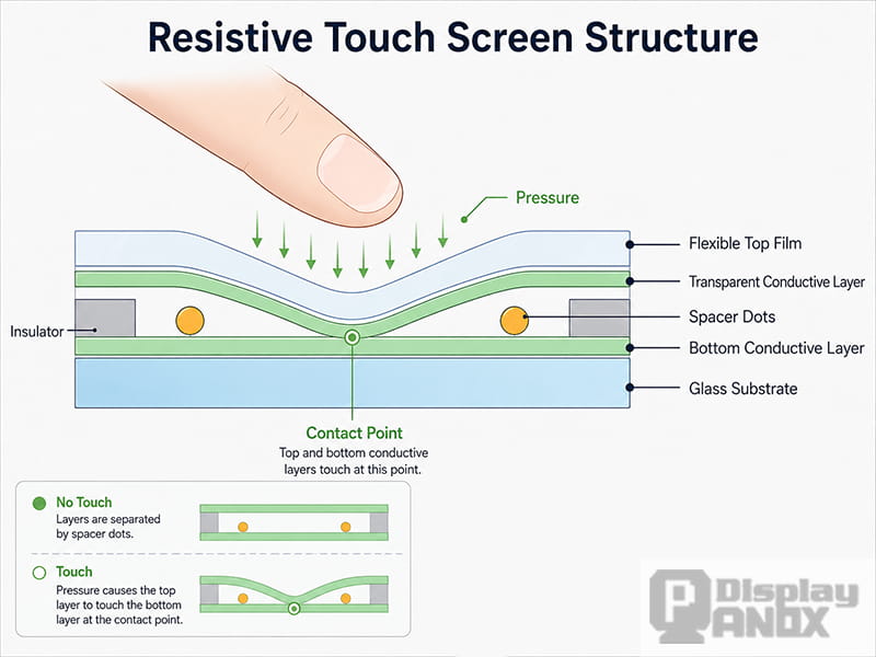
Capacitive and resistive touch screens both provide coordinate input, but they detect touch in different ways.
A capacitive panel measures changes in capacitance. A resistive panel detects pressure that pushes two conductive layers together.
| Feature | Capacitive Touch Screen | Resistive Touch Screen |
|---|---|---|
| Activation method | Change in capacitance | Physical pressure |
| Input force | Light touch | Noticeable pressure |
| Multi-touch | Common with PCAP | Usually limited |
| Gesture support | Strong | Limited on standard panels |
| Finger operation | Excellent | Supported |
| Ordinary plastic stylus | Usually unsupported | Supported |
| Thick-glove operation | Requires suitable design | Generally easier |
| Front surface | Usually rigid glass or plastic lens | Flexible top layer |
| Optical clarity | Generally higher | Additional flexible layers can reduce clarity |
| Scratch resistance | Strong with glass cover | Flexible surface is more vulnerable |
| Water performance | Controller and tuning dependent | Pressure input can be easier in wet conditions |
| Typical applications | Consumer, automotive, medical, kiosk and modern HMI | Legacy industrial, low-cost and pressure-input systems |
A capacitive touch screen is usually the stronger choice when multi-touch, gesture control, visual clarity, a glass front surface, and smartphone-like interaction are priorities.
A resistive touch screen may remain suitable when the interface must respond to almost any object, heavy gloves, fingernails, or a simple pressure-based stylus.
Common Capacitive Touch Screen Applications
Consumer Electronics
Smartphones, tablets, handheld terminals, smart home controllers, gaming products, and portable monitors use capacitive touch for direct, responsive interaction and multi-touch gestures.
Smart Appliances
Ovens, washing machines, coffee machines, air-conditioning controllers, and other appliances can use a sealed glass interface instead of exposed mechanical buttons.
Touch performance in these products may need to account for moisture, cleaning, heat, electrical noise, and operation through decorative overlays.
Industrial HMI
Industrial capacitive touch screens are used in machine controls, test equipment, factory terminals, automation panels, and embedded computers.
Industrial requirements may include:
-
Thick cover glass
-
Glove operation
-
Water rejection
-
High electromagnetic immunity
-
Long-term supply
-
Custom mounting structures
-
High-brightness or sunlight-readable displays
Medical Equipment
Capacitive touch displays can provide smooth interfaces for patient monitors, diagnostic devices, laboratory equipment, and portable medical instruments.
The cover surface can be designed for frequent cleaning, while the controller and firmware can be configured to reduce unintended input from moisture or cleaning fluids.
Automotive Displays
Projected capacitive technology is used in center information displays, instrument panels, rear-seat entertainment systems, climate controls, and other vehicle interfaces.
Automotive projects place strong demands on display-noise immunity, glove operation, temperature range, water handling, latency, functional safety, and long-term reliability.
Retail, POS, and Self-Service Terminals
POS systems, vending machines, ticketing terminals, access-control panels, information kiosks, and ordering stations benefit from a durable glass front and direct on-screen interaction.
The final design may require a customized cover lens, logo printing, vandal-resistant thickness, water protection, and a USB or embedded touch interface.
Wearable and Compact Devices
Smartwatches, fitness trackers, hearables, compact controllers, and other battery-powered products require small touch sensors, low power consumption, reliable gestures, and careful mechanical integration.
Low-power scanning and wake-on-touch functions can help reduce average system power in always-on products.
How to Choose a Capacitive Touch Screen
Selecting a capacitive touch panel should begin with the full product requirements rather than only the display diagonal.
1. Display Size and Active Area
The touch area must align correctly with the display active area. Cover-lens dimensions, viewing window, borders, enclosure overlap, and tolerance stack must also be considered.
2. Required Touch Points
A simple control panel may need only one touch point. A graphical user interface may require five or ten points for gestures and multi-user interaction.
The host operating system and application must support the selected number of touch points.
3. Cover-Lens Material and Thickness
The cover lens affects appearance, impact resistance, optical performance, touch sensitivity, and manufacturing cost.
The final thickness should be confirmed before sensor design and controller tuning.
4. Operating Input
The required input method should be defined clearly:
-
Bare finger
-
Thin glove
-
Medical glove
-
Work glove
-
Winter glove
-
Conductive passive stylus
-
Active pen
-
Wet finger
A statement such as “glove touch required” is too broad for reliable design. Glove material, maximum thickness, and expected environment should be specified.
5. Water and Contaminant Requirements
The project should define whether the system must:
-
Reject droplets
-
Track a wet finger
-
Operate in rain
-
Ignore pooled water
-
Withstand cleaning chemicals
-
Work with saltwater exposure
-
Remain usable with condensation
These conditions require different controller settings and validation procedures.
6. Touch Controller and Interface
Controller selection affects screen size, electrode count, report rate, touch-point count, glove support, water rejection, stylus support, power consumption, operating system compatibility, and interface options.
The host platform must also provide the required driver or protocol support.
7. Bonding Method
Air bonding can reduce cost and simplify replacement. Optical bonding can improve visual performance and mechanical stability.
The most suitable option depends on display size, outdoor readability, impact requirements, production volume, repair strategy, and budget.
8. Display Noise and EMC Requirements
The final touch panel should be tuned with the actual LCD or OLED module, power circuit, enclosure, cables, and main board.
Automotive, medical, appliance, and industrial products may also require formal conducted and radiated immunity testing.
9. Environmental Conditions
Important conditions include:
-
Operating and storage temperature
-
Humidity
-
UV exposure
-
Outdoor sunlight
-
Condensation
-
Vibration
-
Impact
-
Chemical cleaning
-
Electrostatic discharge
The touch sensor, display, adhesive, cover lens, controller, and FPC must all be suitable for the same environment.
10. Customization and Production Volume
A customized capacitive touch screen may involve tooling, sensor-pattern development, cover-glass printing, FPC design, controller tuning, bonding fixtures, samples, and validation.
Early confirmation of annual volume, target cost, prototype quantity, and production schedule helps prevent repeated redesign.
Capacitive Touch Screen Solutions from Panox Display
A reliable touch display should be designed as one complete system. The display panel, touch sensor, cover lens, controller, bonding structure, interface, enclosure, and operating conditions all influence the final user experience.
Panox Display can evaluate a capacitive touch solution around the requirements of the LCD, OLED, or AMOLED display module, including:
-
Display size and resolution
-
Touch active area
-
Cover-lens dimensions and printing
-
Cover-glass shape and thickness
-
Multi-touch requirements
-
Touch-controller selection
-
I²C, SPI, or USB communication
-
FPC and connector design
-
Air bonding or optical bonding
-
Glove and stylus requirements
-
Water and wet-finger performance
-
Brightness and outdoor readability
-
Mechanical and environmental requirements
For a new project, the most useful starting information includes the display specification, mechanical drawing, required touch points, cover-glass design, host platform, interface, operating environment, and expected order quantity.
Conclusion
A capacitive touch screen detects touch by measuring changes in an electric field. Projected capacitive technology has become the main choice for modern interactive displays because it supports light-touch operation, accurate positioning, multi-touch gestures, durable cover glass, and extensive product customization.
Touch quality, however, is determined by more than the sensor itself. Cover-lens thickness, electrode design, controller capability, display noise, bonding, grounding, firmware, gloves, moisture, and the final enclosure all influence performance.
Treating the capacitive touch panel and display as one integrated system creates a more reliable path from prototype to mass production.
Learn more: What Do You Need To Do Before Customizing A Touch?
Frequently Asked Questions
Does a capacitive touch screen require pressure?
No. It detects a change in capacitance rather than mechanical pressure. A light finger touch is normally sufficient.
Can a capacitive touch screen work with gloves?
Yes, when the sensor, cover-lens thickness, controller, and firmware are designed for the specified glove. Glove material and thickness must be defined during development.
Can water damage touch accuracy?
Water can alter the electric field and cause false touches or tracking problems. Controllers with water rejection and wet-finger algorithms can improve operation, but the final assembly still requires testing under the expected conditions.
Can any stylus work on a capacitive touch screen?
No. An ordinary plastic stylus may not register. A conductive passive stylus or a compatible active pen is generally required.
What is a PCAP touch screen?
PCAP means projected capacitive touch screen. It uses a patterned electrode matrix and an electric field that projects through the cover surface. PCAP is commonly used when accurate multi-touch and gesture input are required.
Is PCAP the same as mutual capacitance?
Not exactly. PCAP describes the projected capacitive panel technology. Mutual capacitance is one sensing method used within PCAP systems. PCAP controllers may also use self-capacitance or combine both methods.
Can capacitive touch be used with an OLED display?
Yes. Capacitive touch controllers and sensors can be integrated with OLED and AMOLED display modules as well as TFT LCDs. Display noise, mechanical stack, sensor design, and controller tuning must be evaluated for the selected panel.
Is a capacitive touch screen always better than a resistive touch screen?
No single technology is best for every application. Capacitive touch is generally preferred for multi-touch, gesture control, optical clarity, and a rigid glass surface. Resistive touch remains useful when pressure input, ordinary styluses, or broad glove compatibility are more important.



