







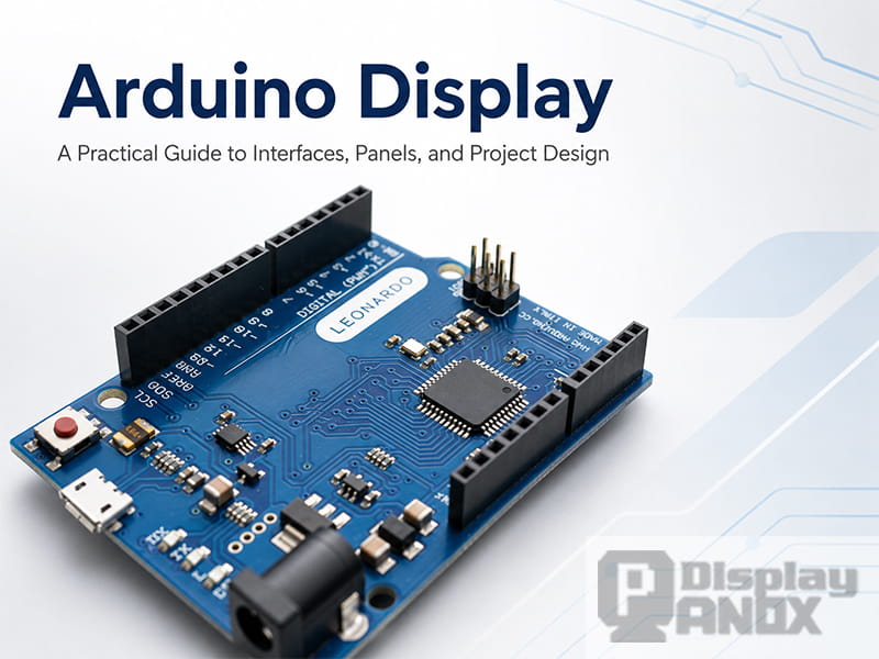
Arduino has become one of the most accessible ways to turn an electronic idea into a working prototype. A few sensors, several lines of code, and a small display are often enough to make a device feel alive. The display is where raw data becomes something people can read, touch, monitor, or control.
An Arduino display usually refers to a display module or display panel used in an Arduino-based project. It may be a small OLED screen showing sensor data, a TFT LCD used for a handheld controller, or a larger high-resolution panel driven through an external controller board. Arduino describes its platform as an easy-to-use hardware and software system for technology and innovation, and the Arduino UNO remains one of the most widely used boards for learning electronics and coding.
For display engineers and product developers, the important question is not only “Can this screen connect to Arduino?” The better question is: what role will Arduino play in the display system? In a simple project, Arduino may directly send drawing commands to a small I2C or SPI display. In a more advanced product, Arduino may handle buttons, sensors, relays, or communication, while a dedicated display controller board drives a higher-resolution LCD or AMOLED panel.
What Does “Arduino Display” Actually Mean?
In many beginner tutorials, an Arduino display is often a small module with a driver IC already mounted on a PCB. These modules usually expose a simple interface such as I2C, SPI, or parallel MCU. They are easy to wire, easy to test, and suitable for text, icons, basic graphics, menus, and sensor dashboards.
In real product development, the term can also describe a broader display solution. A customer may start with Arduino for proof-of-concept testing, then move toward a customized OLED or LCD panel with a touch panel, adapter board, connector, or HDMI/Type-C/MIPI controller. This is especially common when the final product needs a larger screen, higher brightness, better resolution, a special aspect ratio, or a more reliable mechanical structure.
The Panox Display Arduino display panel tag already reflects this wider meaning. The tag page includes interface filters such as I2C, SPI, Parallel, MCU, RGB, MIPI, LVDS, eDP, and HDMI, which shows that “Arduino display” is not limited to one small module type.
Why Display Interface Matters More Than Screen Size
A display panel is never selected by size alone. Two displays with the same diagonal size may require completely different hardware. A 2-inch SPI TFT and a 7-inch MIPI LCD are both “displays,” yet the electrical design, firmware workload, memory requirement, connector, power rail, and initialization process are very different.
A classic Arduino UNO has 14 digital I/O pins, 6 analog inputs, 32 KB flash memory, and 2 KB SRAM. That is enough for many control tasks, small text displays, and simple graphics. It is far from enough for storing or refreshing a full high-resolution video frame locally.
For example, a 1080 × 1920 display using 16-bit color would require about 4 MB for one full frame buffer. This does not mean Arduino cannot be part of a high-resolution display project. It means the system needs the right architecture: Arduino handles control logic, while a display driver IC, bridge IC, or controller board handles the heavy image data.
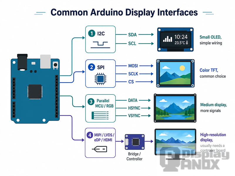
Common Arduino Display Interfaces
I2C Display
I2C is common in compact Arduino display modules because it uses only two signal lines, SDA and SCL. Arduino’s Wire library is designed for I2C communication and is supported across Arduino boards. The protocol is often used for sensors, small displays, motor drivers, and other peripheral devices.
I2C is convenient when wiring space is limited or when multiple low-bandwidth devices share the same bus. It is usually a good fit for small monochrome OLED displays, simple status screens, and low-refresh user interfaces. For full-color animation or fast image updates, SPI or another faster interface is usually a better direction.
SPI Display
SPI is another common interface for Arduino displays. Arduino’s SPI library allows an Arduino board to communicate with SPI devices while the Arduino board works as the controller device.
Compared with I2C, SPI usually supports higher data throughput and is widely used for small TFT LCDs, OLED modules, and graphical displays. It needs more pins than I2C, especially when chip select, data/command, reset, and backlight control pins are included. The advantage is better refresh performance for icons, menus, gauges, waveform previews, and compact graphical interfaces.
Parallel MCU / RGB Display
Parallel MCU displays use more signal lines but can move pixel data faster than simple serial buses. They are useful when a project needs smoother graphics or a larger color display while staying within microcontroller-level design.
RGB displays are closer to a video-style interface. They usually need continuous pixel timing signals and a controller with enough memory bandwidth. Many entry-level Arduino boards are not designed for this kind of display workload, while more powerful microcontrollers or external display controllers can handle it.
MIPI, LVDS, eDP and HDMI Display Solutions
High-resolution modern panels often use interfaces such as MIPI DSI, LVDS, eDP, or HDMI. MIPI DSI is defined as a high-speed serial interface between a host processor and a display module. The MIPI Alliance describes it as a way to achieve high performance, low power, low EMI, reduced pin count, and compatibility across vendors.
These interfaces are common in smartphones, tablets, laptops, automotive displays, wearables, IoT devices, and AR/VR products. In an Arduino-related project, they usually require a bridge board or controller board. The Arduino may still control the product logic, while another processor, HDMI board, or MIPI driver board sends the actual image data to the panel.
OLED, AMOLED and TFT-LCD in Arduino Projects
OLED and LCD technologies behave differently, so the best choice depends on the project rather than the name of the board.
OLED displays are self-emissive, which means each pixel produces its own light. This gives OLED strong contrast, wide viewing angles, and thin module structure. A review article published by the Royal Society of Chemistry notes that OLEDs are important for full-color display panels and lighting because of features such as superior color quality, wide viewing angle, flexibility, and mercury-free manufacture.
AMOLED is a type of OLED display that uses an active-matrix backplane. It is suitable for high-resolution, colorful, thin, and premium-looking interfaces. For Arduino prototypes, AMOLED usually appears in two ways: a small module with a simplified interface, or a higher-resolution panel that needs MIPI and a dedicated driver solution.
TFT-LCD panels use a backlight and liquid crystal layer to form the image. They are widely used because they can offer stable supply, good brightness options, mature manufacturing, and many sizes. IPS TFT-LCD panels are especially useful when the project needs wider viewing angles and full-color graphics.
For industrial, handheld, automotive, smart home, monitoring, and test equipment projects, the decision is often practical: OLED for high contrast and thin form factor, TFT-LCD for brightness, cost control, size variety, and long-term supply.
How Panox Display Products Fit Arduino-Related Development
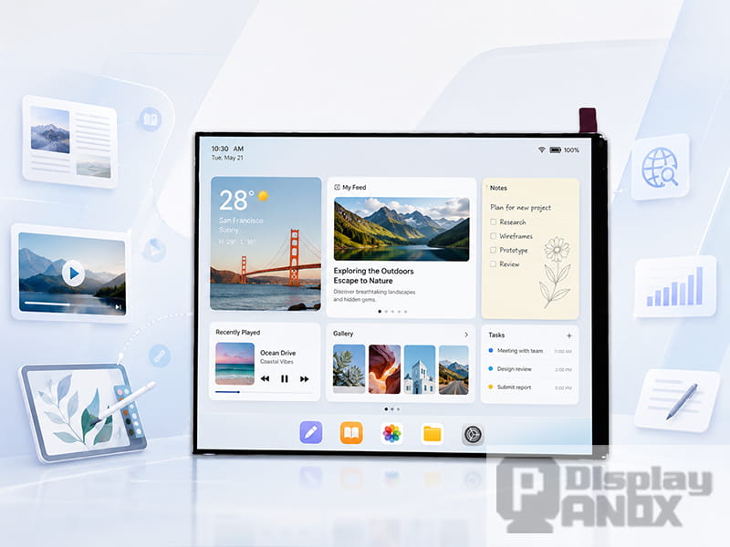
The Arduino tag page on Panox Display currently includes several representative display directions: a 5.5-inch AMOLED panel, a 7.0-inch TFT-LCD panel, and an 8.8-inch long strip TFT-LCD panel. These are not basic two-wire tutorial screens. They are more suitable for developers who need real product-level display quality and are ready to use a display driver, bridge board, or controller board.
The 5.5-inch AMOLED FHD On-cell TP product uses a 1080 × 1920 resolution AMOLED panel with MIPI interface and on-cell PCAP touch. The product page lists AUO as the display brand, MIPI as the interface, 350 cd/m² typical luminance, 10,000:1 minimum contrast ratio, and an operating temperature range of -40 to 85 °C.
The 7.0-inch TFT-LCD product is a 1200 × 1920 WUXGA panel with MIPI interface. The page describes it as a JDI LTPS TFT-LCD display with 332 PPI, suitable for tablet, digital product, industrial machine, vehicle, and electronic album applications. Panox also notes that it can provide an HDMI-to-MIPI DSI controller board for this 7-inch LCD.
The 8.8-inch long strip LCD uses a 1920 × 480 resolution stretched format and is positioned for secondary PC displays, vehicle screens, and monitoring applications. Panox lists a 600 cd/m² typical luminance, 60 Hz refresh rate, MIPI 4-lane signal type, and an HDMI-to-MIPI DSI controller board option tested with Raspberry Pi 3B.
For Arduino-related development, these products are especially relevant when the project needs a display that looks closer to a finished device than a breadboard demo. A simple Arduino board may not directly drive these high-resolution MIPI panels, yet it can still be used in the system for input, sensing, control, serial communication, or interaction with a separate display controller.
Choosing the Right Arduino Display Panel
A good Arduino display choice starts with the application. A temperature monitor, battery tester, wearable prototype, handheld controller, car auxiliary display, and industrial HMI may all need different display structures.
For a small sensor device, a compact I2C OLED or SPI LCD can be enough. It keeps the wiring simple and the firmware manageable. For a handheld product with icons, menus, and richer color, an SPI TFT or MCU-interface LCD may be more practical. For a high-resolution visual interface, such as a 7-inch control panel or a long strip monitoring display, a controller-board solution becomes more realistic.
The next step is to check electrical compatibility. Developers should confirm logic voltage, supply rails, connector type, pin pitch, initialization code, driver IC, touch interface, and backlight requirements. Touch is often handled separately through I2C or SPI, even when the display image data uses MIPI or another high-speed interface. Espressif’s MIPI-DSI documentation also describes touch data being sent back to the host through I2C or SPI while frame color data is transmitted through the display interface.
Mechanical design is just as important. A display panel may need a cover glass, touch panel, FPC extension, adapter board, mounting structure, enclosure space, optical bonding, or brightness adjustment. This is where a display supplier becomes more useful than a single module seller.
Panox Display states that it can provide display datasheets, drawings, IC datasheets, circuit schematics, connectors, adapter boards, customized touch panels, and controller/driver boards for many LCD/OLED products.
Direct Drive or Controller Board?
For many Arduino display projects, the biggest design decision is whether to drive the display directly or use a controller board.
Direct drive is suitable when the display is small, the interface is simple, and the refresh requirement is modest. It gives developers more control over the firmware and can reduce hardware cost. The tradeoff is that the Arduino must handle initialization, drawing, timing, and data transfer within its limited resources.
A controller board is more suitable when the display is high-resolution, MIPI-based, touch-enabled, or intended to behave like a monitor. In this architecture, the display board accepts HDMI, Type-C, VGA, DVI, DP, or another input, then converts the signal to the panel interface. Panox’s Arduino tag page also mentions customized controller/driver boards with VGA, HDMI, DVI, DP, Type-C video input and output interfaces such as MIPI, RGB, LVDS, and eDP.
This approach is often cleaner for product demos, industrial prototypes, PC sub-displays, Raspberry Pi projects, and any system where the visual interface is too complex for a small microcontroller to render alone.
Typical Applications for Arduino Display Panels
Arduino display panels are used in far more than hobby projects. They can appear in test equipment, lab instruments, smart home controls, battery monitors, environmental sensors, compact HMIs, educational kits, art installations, automotive auxiliary displays, and proof-of-concept devices.
Small OLED displays work well for compact status feedback. TFT-LCDs are better when the interface needs color, image content, or a larger active area. AMOLED panels are attractive for premium handheld devices, wearable-style interfaces, or prototypes where contrast and thin structure matter. Long strip LCDs are useful for dashboards, secondary monitors, PC hardware monitoring, vehicle information displays, and narrow installation spaces.
The key is to treat the Arduino display as part of a complete system. The screen, controller, firmware, enclosure, touch panel, optical performance, and power design all affect the final user experience.
Final Thoughts
An Arduino display can be a small plug-in OLED module, a compact TFT screen, or a high-resolution display panel supported by a controller board. The right choice depends on the application, interface, resolution, available memory, refresh speed, touch requirements, and mechanical design.
For simple projects, I2C and SPI displays are fast to develop and easy to debug. For advanced prototypes and product-level interfaces, MIPI LCD, AMOLED, long strip LCD, HDMI controller boards, and customized touch solutions give developers more room to build a polished device.
Panox Display supplies small and medium-sized OLED/LCD panels, including AMOLED, TFT-LCD, long strip displays, touch panels, connectors, adapter boards, and controller board solutions. For Arduino-related development, this means the display path can grow from a simple prototype to a more complete embedded display system without changing the whole product concept halfway through.



