


1. LCD Hardware Operating Principle
1.1 How to Represent Pixel Colors
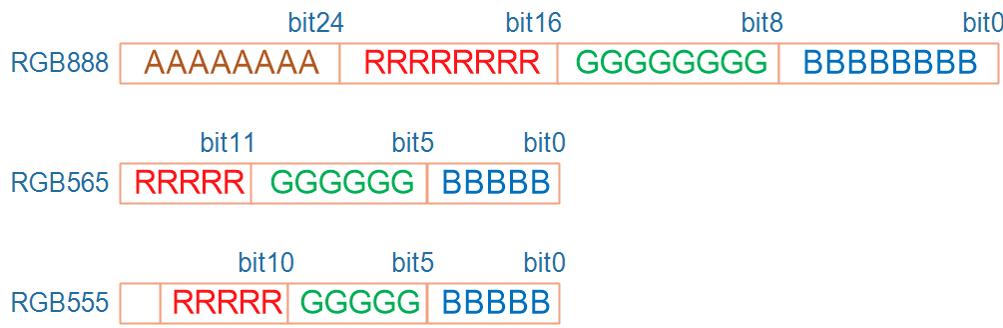
We know that all colors in nature can be represented by red, green, and blue. In the field of computers, colors can be represented by data, such as commonly used formats like RGB888, RGB565, RGB555, and so on:RGB888: 8 bits for red, 8 bits for green, 8 bits for blue.
RGB565: 5 bits for red, 6 bits for green, 5 bits for blue.
RGB555: 16-bit data with 5 bits for red, 5 bits for green, 5 bits for blue, wasting one bit.
Additionally, we need to understand the meaning of the pixel unit bpp:
- bpp: bits per pixel, indicating how many bits are used to represent each pixel.
- 24bpp: Actually uses 32 bits, where 8 bits are unused, and the remaining 24 bits represent red (R), green (G), and blue (B) with 8 bits each.
- 16bpp: Includes formats like RGB565 and RGB555.
1.2 LCD Screen Working Principle
An LCD is composed of individual pixels: each row has xres pixels, and there are yres rows. The resolution is xres * yres. As long as we can control the color of each individual pixel, we can display text and images on the LCD.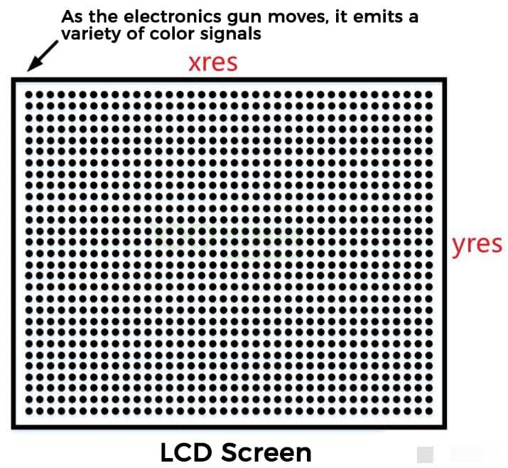
Assume the image above is an LCD screen. The small black dots on the screen represent pixels. Each row has several dots. Imagine an electron gun located behind a pixel, firing red, green, and blue light in various proportions to form any color. The electron gun moves behind the pixels, emitting various colors as it moves from left to right. Once it reaches the right edge, it jumps to the beginning of the next row and continues moving from left to right. This repeats until it reaches the bottom-right pixel, after which it jumps back to the origin. This process cycles at a certain frequency to display various images on the LCD.
Question 1: How does the electron gun move?
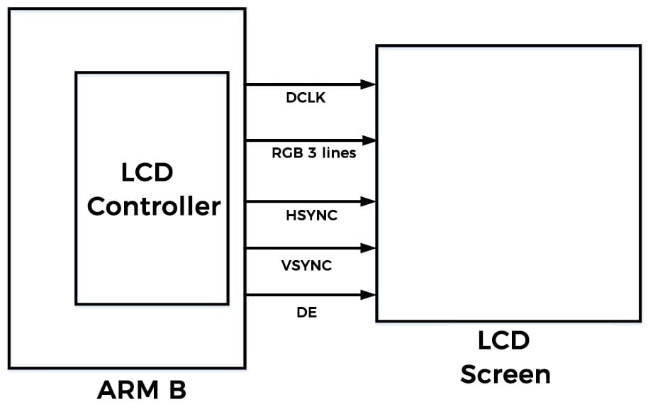
Answer: There is a pixel clock signal line (DCLK) connected to the screen. Every time a pixel clock signal (DCLK) is received, the electron gun moves one pixel.
Question 2: How is the color fired by the electron gun determined?
Answer: There are three sets of signal lines for red, green, and blue (RGB) connected to the screen. These three signal lines (RGB) transmit the color information.
Question 3: How does the electron gun know when to jump to the next row?
Answer: There is a horizontal synchronization signal line (HSYNC) connected to the screen. When the horizontal synchronization signal (HSYNC) is received, the electron gun jumps to the far-left position of the next row.
Question 4: How does the electron gun know when to jump back to the origin?
Answer: There is a vertical synchronization signal line (VSYNC) connected to the screen. When the vertical synchronization signal (VSYNC) is received, the electron gun jumps from the bottom-right corner back to the top-left corner (the origin).
Question 5: How does the electron gun know that the color determined by the three sets of signal lines (RGB) is valid?
Answer: There is a data enable signal line (DE) connected to the screen. When the data enable signal line (DE) is received, the electron gun knows that the color determined by the three sets of signal lines (RGB) is valid and can be fired to the pixel.
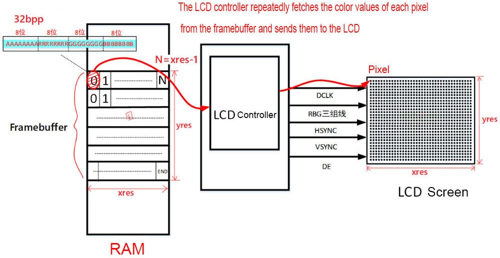
Below is a block diagram of the development board, LCD controller, and LCD screen.
1.3 How to Send Colors to the LCD
Assume that each pixel's color is represented by 16 bits. For an LCD with xres * yres pixels, the required memory is: xres * yres * 16 / 8. This is the amount of memory needed to store the color data for all pixels. This memory is called the framebuffer (some chips refer to it as GRAM).
- Each data block in the framebuffer corresponds to one pixel.
- The size of each data block may be 16 bits or 32 bits, depending on the LCD's pixel color format.
- Once the LCD hardware is set up, you just need to write the color data into the framebuffer.
- The LCD controller inside the chip, driven by the LCD driver program, will take care of the rest.
- Where is the framebuffer located? >>> Usually in RAM storage, such as DDR.
- Who sends the framebuffer data to the LCD? >>> The chip's internal LCD controller.
2. LCD Screen Timing Analysis
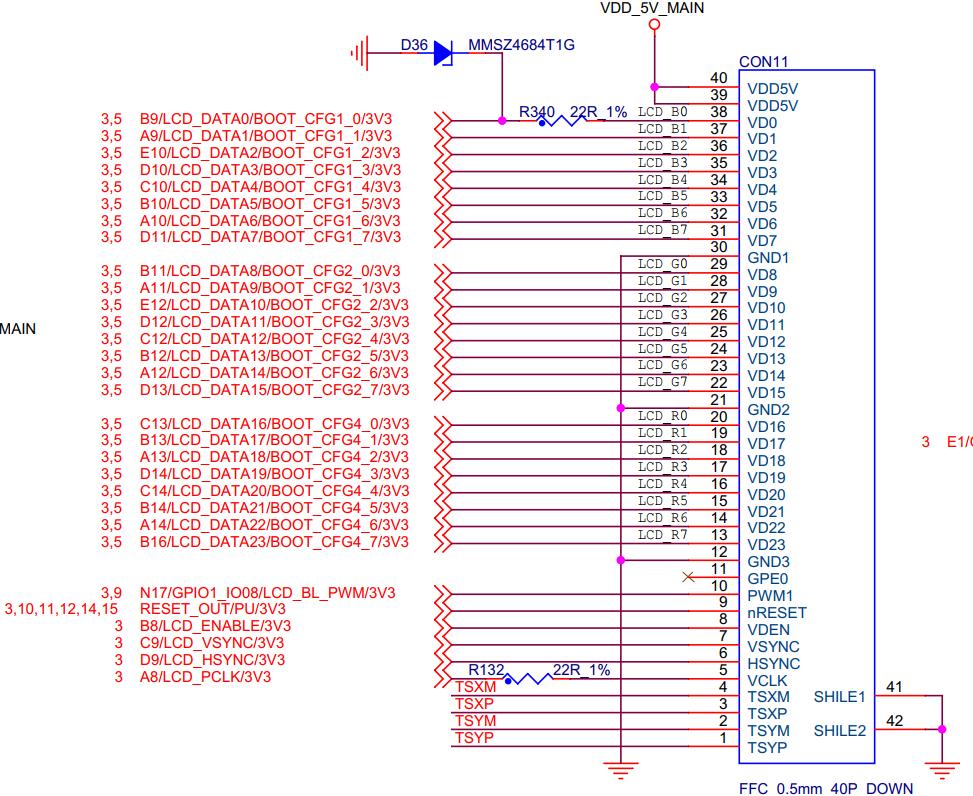
2.1 Common TFT-RGB Interface for MPUs
Generally, microcontrollers (MCUs) use an 8080 interface LCD module, but this interface is not suitable for high resolutions. Higher resolutions require larger framebuffers, and these modules typically use SRAM, which is expensive. The advantage is that they are easy to use, and you mainly need to refer to the chip manual to understand how to transmit data or commands.Therefore, for higher-resolution LCD screens, TFT RGB interface LCD modules are usually used. These modules typically use DDR or SDRAM as the framebuffer, which is relatively cheaper. However, using this solution often requires studying the chip manual's LCD controller, which can be more complex. Below is a schematic diagram of the TFT RGB interface hardware.
2.2 LCD Screen Parameter Analysis
Earlier, we introduced several important signals in the LCD hardware working principle. These are described in the datasheet, as shown below.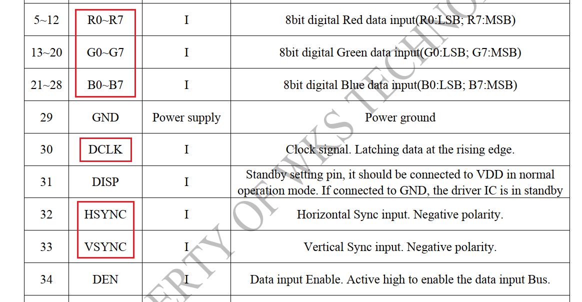
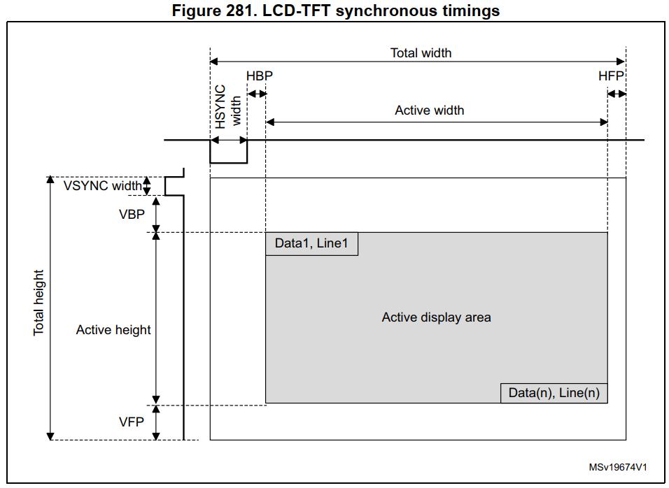
Here, we focus on analyzing the SYNC synchronization signal timing parameters. The datasheet provides screenshots of the SYNC synchronization signal and its timing, as shown below.
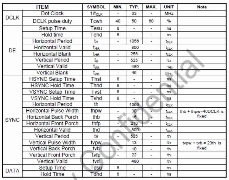
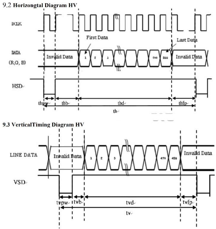
2.2.1 HSYNC (Horizontal Synchronization Signal) Timing Analysis
- th: Total number of pixels in each row (including invisible areas), here it equals 1056.
- thpw: Minimum pulse width in the horizontal direction (if this pulse width is too short, the electron gun might not respond properly); 30.
- thb: The number of pixels the electron gun can move before the first horizontal pixel of the resolution (front porch, invisible); 16.
- thfp: The number of pixels the electron gun can move after the last horizontal pixel of the resolution (back porch, invisible); 210.
- thd: The number of pixels in each row, equal to 800 in a resolution of 800 x 480 (active pixels); 800.
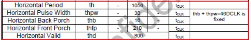
2.2.2 VSYNC (Vertical Synchronization Signal) Timing Analysis
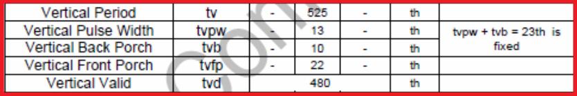
- tv: Total number of pixels in each column (including invisible areas), here it equals 525.
- tvpw: Minimum pulse width in the vertical direction (if this pulse width is too short, the electron gun might not respond properly); 13.
- tvb: The number of pixels the electron gun can move before the first vertical pixel of the resolution (upper porch, invisible); 10.
- tvfp: The number of pixels the electron gun can move after the last vertical pixel of the resolution (lower porch, invisible); 22.
- tvd: The number of pixels in each column, equal to 480 in a resolution of 800 x 480 (active pixels); 480.