







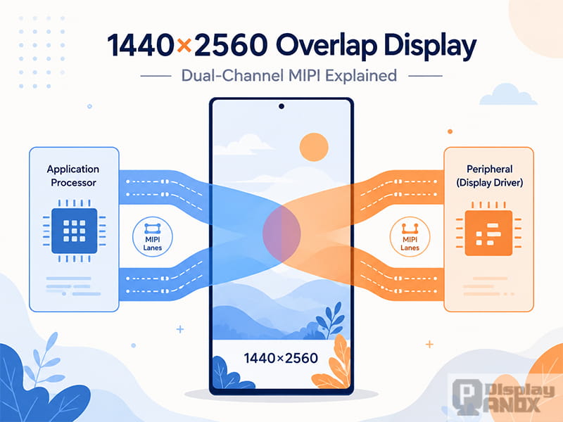
A 1440×2560 overlap display is a high-resolution panel driven through two coordinated display links, with both links transmitting a small shared section of image data near the point where the frame is divided.
The term is most often associated with dual-channel MIPI DSI systems. Instead of sending the entire 1440×2560 frame through one interface, the display controller separates the image into left and right regions. One MIPI link carries the first region, while the second link carries the remaining region. In overlap mode, the two data regions extend slightly across the dividing line, creating a narrow band of repeated pixels.
This arrangement is different from a dual-monitor desktop, an image overlay or two physical screens placed on top of each other. It is a method of transporting and mapping one continuous image across multiple high-speed display channels.
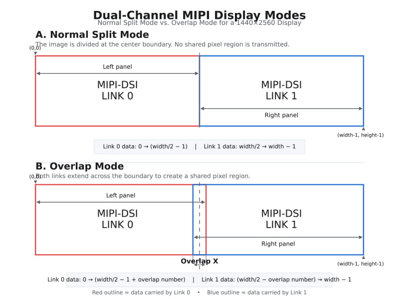
double channel overlap display
What Does 1440×2560 Mean?
A 1440×2560 display contains:
-
1,440 pixels across the horizontal axis
-
2,560 pixels along the vertical axis
-
3,686,400 addressable pixels in total
-
A native 9:16 portrait aspect ratio
When the panel is rotated, the same pixel matrix may be described as 2560×1440 in landscape orientation. The total resolution remains unchanged.
This resolution is commonly grouped into the QHD or WQHD class. However, exact pixel dimensions are more useful than general labels such as “2K,” especially when configuring display timing, controller firmware or image orientation.
On a compact panel, 1440×2560 can produce a very high pixel density. That makes the format suitable for near-eye displays, compact projectors, optical instruments, resin 3D printers and other systems in which the display is viewed closely or optically enlarged.
What Does “Overlap Display” Mean?
In this context, overlap does not describe an image defect. It refers to the way two display-output channels share a small section of the frame.
A dual-channel controller first divides the image along a vertical boundary:
Normal dual-channel mode:

MIPI DSI Link 0             MIPI DSI Link 1
[ Left image region ][ Right image region ]
                       ↑
                  Split boundary
In normal mode, the first link ends at the center boundary and the second link begins immediately after it.
An overlap configuration extends both regions beyond that boundary:
Dual-channel overlap mode:

MIPI DSI Link 0
[ Left image region -----------]
                       [----------- Right image region ]
                              MIPI DSI Link 1
                         ↑
                  Shared pixel region
Both links therefore contain some of the same horizontal image data.
The Rockchip RK3288 VOP technical reference manual describes this as double channel overlap display. In its left-right dual-channel mode, one output carries left-panel data and the other carries right-panel data. When overlap mode is enabled, each output extends into the central region by a programmable amount.
Why Use Two MIPI DSI Links?
MIPI DSI is a high-speed serial connection between a host processor and a display module. It is designed to deliver high display performance with relatively few pins, low power consumption and low electromagnetic interference. It is widely used in smartphones, embedded displays, automotive systems, wearables and VR or AR devices.
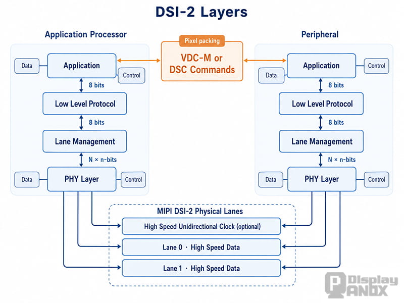
Schematic Diagram of the MIPI DSI-2 Protocol Layer
A high-resolution display requires a substantial amount of image data to be transmitted every second. The active RGB888 image payload for a 1440×2560 panel operating at approximately 60.3 Hz is about:
1440 × 2560 × 60.3 × 24 bits
≈ 5.33 Gbit/s
This figure covers active pixel data only. Blanking intervals, packet headers and other transmission overhead increase the actual link requirement.
Dividing the frame across two MIPI ports reduces the amount of image data that each link must carry. With two four-lane ports, the active payload works out to roughly 667 Mbit/s per lane before protocol and blanking overhead.
The LS055R1SX04 specification, for example, defines two four-lane MIPI DSI ports operating at 850 Mbit/s per lane. Its specified video timing supports a 1440×2560 image at approximately 60.3 Hz.
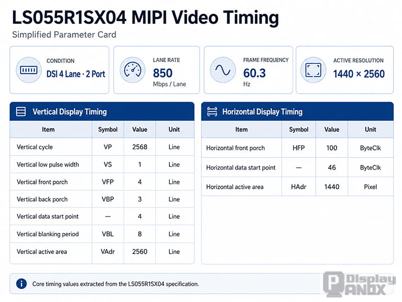
Dual-channel operation can therefore make a high-resolution panel practical without forcing one DSI interface to carry the full frame bandwidth.
Normal Split Mode vs. Overlap Mode
The two modes use the same complete source frame but map its center boundary differently.
| Mode | Link 0 | Link 1 | Shared Pixels |
|---|---|---|---|
| Normal split mode | Left part of the frame | Right part of the frame | None |
| Overlap mode | Left part plus additional boundary pixels | Right part plus additional boundary pixels | Yes |
For an image width of W, a simplified normal split can be expressed as:
Link 0: pixel 0 to W/2 − 1
Link 1: pixel W/2 to W − 1
The Rockchip documentation describes overlap operation using the following ranges:
Link 0: pixel 0 to W/2 − 1 + overlap value
Link 1: pixel W/2 − overlap value to W − 1
This makes the two channel ranges intersect near the center of the image.
The meaning of an overlap register is controller-specific. Some documentation expresses the value as an extension on each side, while other implementations may describe the final shared width. Register values should therefore be interpreted according to the selected SoC or timing-controller manual rather than copied from another platform.
Why Is an Overlap Region Needed?
A shared pixel region may be required when the panel or its internal driver architecture expects both data paths to receive information around the image boundary.
Possible reasons include:
Matching the Panel’s Internal Mapping
A panel with two DSI receiver paths may divide its source-driver columns into two groups. The boundary between those groups does not always correspond to a simple one-pixel cut. An overlap region allows the host output to match the panel’s internal data assignment.
Supporting Dual Display Driver ICs
Some high-resolution displays use more than one display driver or receiving section. A small shared region may be part of the manufacturer’s recommended mapping between the host and those internal components.
MIPI provides application guidance for systems supporting dual display-driver ICs, reflecting the use of multiple receiving paths in advanced panel architectures.
Meeting Controller-Specific Output Requirements
The overlap may be generated by the display controller rather than by the panel itself. The VOP, timing controller or bridge IC must be configured to produce the horizontal ranges expected by the receiving hardware.
Maintaining a Continuous Image Boundary
Correct overlap mapping helps the two channel outputs represent one continuous source image. It does not automatically improve image quality, but an incorrect mapping can produce a visible discontinuity, duplicated columns or missing columns at the center.
The overlap width is therefore a compatibility parameter, not a general image-enhancement setting. A larger overlap is not inherently better.
Is an Overlap Display the Same as a Dual-Screen Display?
No.
A conventional Windows dual-screen configuration uses one computer to control two physical monitors. The operating system can duplicate the same desktop, extend the desktop across both displays or use only one screen. Each monitor remains an independent display device with its own resolution and position.
A 1440×2560 overlap display is normally one physical panel presenting one continuous image. Its two MIPI links operate below the operating-system desktop level.
| Technology | Physical displays | Image structure | Main purpose |
|---|---|---|---|
| Windows extended display | Two or more | Separate desktop areas | Multitasking |
| Windows duplicate display | Two or more | Same complete image on each monitor | Presentation |
| Dual-channel split display | Usually one | One frame divided between two links | Bandwidth distribution |
| Dual-channel overlap display | Usually one | Divided frame with a shared boundary region | Panel and controller mapping |
Changing the Windows projection mode with Win + P does not configure MIPI overlap. The overlap setting belongs to the display controller, bridge chip, kernel driver or embedded firmware.
Is Overlap Display the Same as Overlay Display?
These terms are easy to confuse but refer to different operations.
Overlap Display
Overlap duplicates a narrow spatial region between two output channels. It concerns how one frame is divided and transmitted.
Overlay Display
Overlay combines multiple image layers before the final frame is sent to the panel. Examples include:
-
A video layer
-
A graphical user interface
-
A hardware cursor
-
Subtitles
-
Transparent controls
-
Alpha-blended windows
The Rockchip VOP documentation treats overlay processing and dual-channel overlap as separate functions. Overlay belongs to image composition; overlap belongs to channel mapping.
How a 1440×2560 Dual-Channel Panel Is Connected
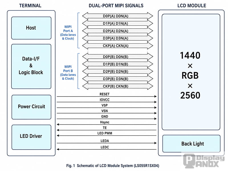
A dual-channel panel typically includes two groups of MIPI DSI signals.
Each group may contain:
-
One differential clock pair
-
Four differential data lanes
-
Ground connections
-
Shared reset and power signals
-
Tearing-effect or synchronization signals
The LS055R1SX04 uses a 50-pin, 0.4 mm-pitch board-to-board connector. Its interface table identifies separate Port A and Port B signals, with each port providing one clock pair and four data-lane pairs.
This interface should not be mistaken for a standard HDMI connector. A bare MIPI LCD cannot normally receive HDMI video directly. A controller or bridge board must convert the source signal and generate:
-
Correct MIPI lane data
-
Panel-specific display timing
-
Initialization commands
-
Reset sequence
-
Power sequence
-
Image orientation
-
Dual-link mapping
-
Overlap configuration, where required
A controller board that supports 2560×1440 output does not automatically support every 1440×2560 MIPI panel. The panel model, driver IC, lane configuration and firmware must also match.
What Must Be Configured in the Display Controller?
A reliable 1440×2560 overlap display implementation requires more than setting the resolution.
1. Dual-Channel Enable
The display controller must be placed in a mode that sends two coordinated output buses to two MIPI DSI transmitters.
On the RK3288 VOP, the relevant documentation describes a doub_channel_en control for left-right dual-channel output.
2. Split Direction
The controller and panel must agree on whether the image is divided left-right or top-bottom.
The RK3288 implementation documented in the VOP manual supports the left-right arrangement. Other SoCs or bridge ICs may provide different split options.
3. Channel Order
Link 0 and Link 1 must be connected to the correct panel ports. Reversing them can swap the two image halves or prevent correct initialization.
4. Overlap Width
The overlap value must match the display architecture. An incorrect value can leave a repeated or missing vertical strip near the center.
5. Horizontal Timing
The active width, blanking periods and link-specific output widths must remain consistent with the panel timing requirements.
6. Vertical Timing
Both links must start and end each frame together. A mismatch may produce tearing, instability or different frame phases across the panel.
7. Pixel Format
RGB888, RGB666 and other data formats have different bandwidth requirements. The panel and host must use the same format.
8. Initialization Sequence
Many MIPI panels require model-specific DCS or manufacturer commands before normal image transmission begins.
9. Power Sequence
Logic voltage, positive and negative analog rails, reset and image data must be enabled in the correct order. The LS055R1SX04 specification includes separate IOVCC, VSP and VSN supplies as well as a defined reset and initialization sequence.
Common 1440×2560 Overlap Display Problems
A Vertical Line Appears in the Center
A narrow central line often indicates a channel-boundary problem.
Possible causes include:
-
Incorrect overlap width
-
One missing image column
-
Repeated columns
-
Reversed link assignment
-
Different active-width values on the two links
-
Panel timing that does not match the controller firmware
A solid-color test pattern and a numbered horizontal grid can make the boundary easier to inspect.
The Two Image Halves Are Swapped
Port A and Port B may be connected in reverse, or the controller may assign Link 0 and Link 1 in the opposite order expected by the panel.
Correcting this issue may require changing the physical routing, device-tree configuration or display-controller register settings.
One Half of the Panel Is Blank
This usually indicates that one link is not transmitting or one receiving port has not been initialized.
Check:
-
MIPI clock activity on both links
-
Lane count
-
Reset timing
-
Connector continuity
-
Link enable registers
-
Power rails
-
Panel initialization commands
The Center Region Is Duplicated
The overlap value may be larger than the panel expects, or the panel may require normal split mode rather than overlap mode.
Overlap should only be enabled when supported by the selected controller-panel combination.
The Image Is Unstable at 60 Hz
The lane rate may not leave enough margin for active data, blanking and protocol overhead. Incorrect porch values, signal-integrity problems or mismatched D-PHY settings can also cause instability.
A 1440×2560 RGB888 stream at around 60 Hz already carries more than 5 Gbit/s of active pixel data. Lane-rate calculations should include the complete video timing rather than active pixels alone.
The Panel Works with One Board but Not Another
Two controller boards may use the same connector and advertise the same resolution while running different panel programs.
The Panox Display product page notes that LS055R1SX03 and LS055R1SX04 controller programs are different and recommends confirming the board program before connecting the panel.
Where Are 1440×2560 Overlap Displays Used?
VR and Head-Mounted Displays
Near-eye optical systems benefit from high pixel density because lenses magnify the panel. Dual MIPI links can provide the bandwidth needed to refresh a compact QHD image source.
The overlap described here is the overlap between data channels. It should not be confused with binocular overlap, which describes the portion of a VR field of view visible to both eyes.
Compact Projection Systems
A high-density LCD can act as an image-forming component in a projector. The panel resolution determines the available pixel grid, while the optical result also depends on illumination, transmittance, cooling, lens quality and alignment.
Resin 3D Printers
In an MSLA printer, the LCD works as a programmable exposure mask. A high-resolution panel can create a fine XY pixel grid, although final print accuracy also depends on resin response, light uniformity and mechanical control.
For this application, the original LCD backlight is normally removed so that the printer’s exposure source can pass through the panel.
Embedded Imaging Equipment
Portable microscopes, inspection tools, laboratory instruments and custom viewing systems may use compact QHD panels when a dense image is required in a limited area.
Display Development Platforms
A dual-channel panel and matched bridge board can be used to evaluate MIPI timing, image splitting, controller firmware and optical-system prototypes.
A 5.5-Inch 1440×2560 MIPI LCD Example
Panox Display supplies a 5.5-inch 1440×2560 MIPI TFT-LCD based on the LS055R1SX03 and LS055R1SX04 panel family.
The LS055R1SX04 specification lists:
| Item | Specification |
|---|---|
| Native resolution | 1440×2560 |
| Active area | 68.04×120.96 mm |
| Display mode | Normally black |
| Interface | Dual-port MIPI DSI |
| MIPI configuration | Two ports, four data lanes per port |
| Specified lane rate | 850 Mbit/s per lane |
| Frame frequency | Approximately 60.3 Hz |
| Connector | 50-pin, 0.4 mm pitch |
| Panel orientation | Portrait |
The panel includes separate Port A and Port B MIPI signal groups, making it suitable for controller designs that divide the image across two DSI links. Whether overlap mode is required depends on the controller architecture and the panel-driving program; dual-port hardware alone does not prove that a particular host configuration should use a non-zero overlap value.
Panox Display can also provide a matched controller board for display evaluation. For resin 3D-printing projects, the panel can be supplied with its original backlight removed and with a suitable cover-glass assembly.
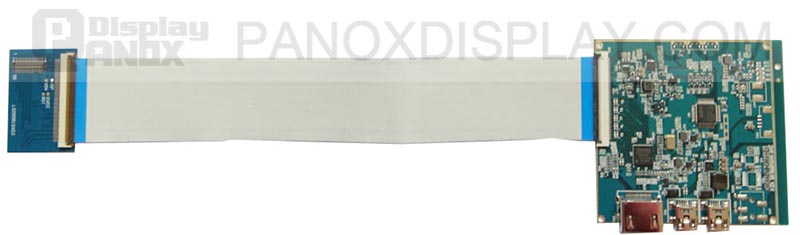
HDMI Controller Board
How to Select a Controller for a 1440×2560 Overlap Display
The following items should be confirmed before hardware is ordered:
-
Exact LCD model
Similar model numbers may use different initialization programs. -
Number of MIPI ports
A single-port controller cannot directly drive a panel that requires two independent DSI inputs. -
Lanes per port
Verify whether each link uses two or four data lanes. -
Maximum lane rate
The link must support the complete video timing with adequate signal margin. -
Dual-channel split support
The controller must be able to divide one framebuffer between two outputs. -
Overlap configuration
Check whether the controller provides a programmable overlap region and whether the panel requires it. -
Panel initialization support
Correct commands must be issued before video transmission. -
Power-rail generation
The controller solution must provide or coordinate all required panel voltages. -
Orientation and rotation
Confirm whether the source supplies 1440×2560 portrait data or rotated 2560×1440 content. -
Connector and pin assignment
Matching pin count does not guarantee matching electrical connections.
Conclusion
A 1440×2560 overlap display is best understood as a complete QHD image delivered through two coordinated display channels. The controller divides the frame into left and right regions, then repeats a configurable number of pixels around the central boundary when the panel architecture requires overlap mode.
The overlap region is only one part of the design. Stable operation also depends on lane rate, blanking timing, channel order, initialization commands, voltage sequencing and the exact mapping expected by the LCD.
For that reason, resolution alone is not enough to determine compatibility. The panel model, controller firmware and dual-link configuration must be evaluated together. When these parameters are correctly matched, dual-channel MIPI provides an efficient way to drive compact, high-density displays for VR, projection, embedded imaging and resin 3D-printing systems.
Learn more: MIPI DSI PCB Layout Guidelines for Reliable Display Interfaces
Frequently Asked Questions
What is a 1440×2560 overlap display?
It is typically a 1440×2560 panel driven by two coordinated display links. The frame is divided into two regions, and the links transmit a small shared pixel area at the boundary.
Is overlap mode required for every dual-MIPI panel?
No. Some panels use a direct left-right split with no repeated pixels. Others require an overlap region. The correct mode must be obtained from the panel, controller or bridge documentation.
Does overlap mean that two complete images are shown?
No. The system still displays one complete image. Only a narrow part of the transmitted data is repeated across the two links.
Is overlap display the same as dual display?
No. Dual display usually refers to two physical screens. A dual-channel overlap display is commonly one panel receiving different parts of the same frame through two links.
Is overlap display the same as overlay display?
No. Overlap concerns duplicated boundary pixels between output channels. Overlay concerns the composition of multiple graphical layers.
Why does a 1440×2560 display use two MIPI ports?
Two ports divide the high-resolution data load. This reduces the required payload carried by each MIPI link and can match a panel designed with two receiving paths.
Can HDMI drive the panel directly?
No. A bare MIPI panel requires a compatible MIPI DSI host or an HDMI-to-MIPI bridge board programmed for the exact LCD model.
Can the overlap value be increased to improve image quality?
No. The overlap value must match the panel mapping. An excessive value can duplicate image columns, while an insufficient value can leave missing data or a visible center boundary.
Can a 1440×2560 overlap display be used with Windows?
It can appear as a normal monitor when connected through a suitable controller board. Windows usually sees the controller’s HDMI or DisplayPort input, while the controller handles the dual-MIPI split internally.



